Tracking 2
Multi-Camera Systems
Type of multi-camera systems
Stereo-camera system (narrow baseline)
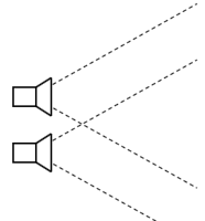
- Close distance and equal orientation
- An object’s appearance is almost the same in both cameras
- Allows for calculation of a dense disparity map
Wide-baseline multi-camera system
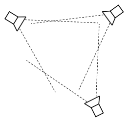
Arbitrary distance and orientation, overlapping field of view
An object’s appearance is different in each of the cameras
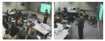
Allows for 3D localization of objects in the joint field of view
Multi-camera network
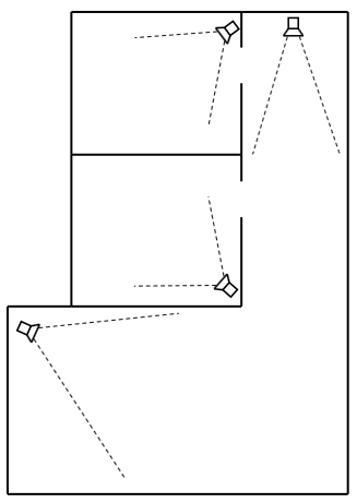
- Non-overlapping field of view
- An object’s appearance differs strongly from one camera to another
3D to 2D projection: Pinhole Camera Model
Summary:
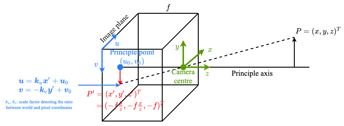
$$ \frac{y^{\prime}}{-f}=\frac{y}{z} \Rightarrow y^{\prime}=\frac{-f y}{z} $$
$$ \frac{x^{\prime}}{-f}=\frac{x}{z} \Rightarrow x^{\prime}=\frac{-f x}{z} $$
Pixel coordinates $(u, v)$ of the projected points on image plane
In matrix formulation: $$ \left(\begin{array}{l} u \\ v \end{array}\right)=\left(\begin{array}{cc} k_{u} & 0 \\ 0 & -k_{v} \end{array}\right)\left(\begin{array}{l} x^{\prime} \\ y^{\prime} \end{array}\right)+\left(\begin{array}{l} u_{0} \\ v_{0} \end{array}\right) $$ Perspective Projection
internal camera parameters $$ \begin{array}{l} \alpha_{u}=k_{u} f \\ \alpha_{v}=-k_{v} f \\ u_{0} \\ v_{0} \end{array} $$
- have to be known to perform the projection
- they depend on the camera only
- Perform calibration to estimate
Calibration
Intrinsics parameters: describe the optical properties of each camera (“the camera model”)
- $f$: focal length
- $c_x, c_y$: the principal point (“optical center”), sometimes also denoted as $u_0, v_0$
- $K_1, \dots, K_n$: distortion parameters (radial and tangential)
Extrinsic parameters: describe the location of each camera with respect to a global coordinate system
- $\mathbf{T}$: translation vector
- $\mathbf{R}$: $3 \times 3$ rotation matrix
Transformation of world coordinate of point $p^* = (x, y, z)$ to camera coordinate $p$: $$ p = \mathbf{R} (x, y, z)^T + \mathbf{T} $$ Calibration steps
- For each camera: A calibration target with a known geometry is captured from multiple views
- The corner points are extracted (semi-)automatically
- The locations of the corner points are used to estimate the intrinsics iteratively
- Once the intrinsics are known, a fixed calibration target is captured from all of the camerasextrinsics
Triangulation
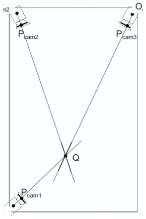
- Assumption: the object location is known in multiple views
- Ideally: The intersection of the lines-of-view determines the 3D location
- Practically: least-squares approximation