Access Networks
Introduction
Circuit Switching
„Circuit“
- Logical circuit with reserved resources for data transmission
- no physical cable!
- No meta data (header, appendix) required during data exchange
- No buffer overflows in intermediate systems!
- But: possibly bad resource utilization
- Use case: telephone network
ISDN
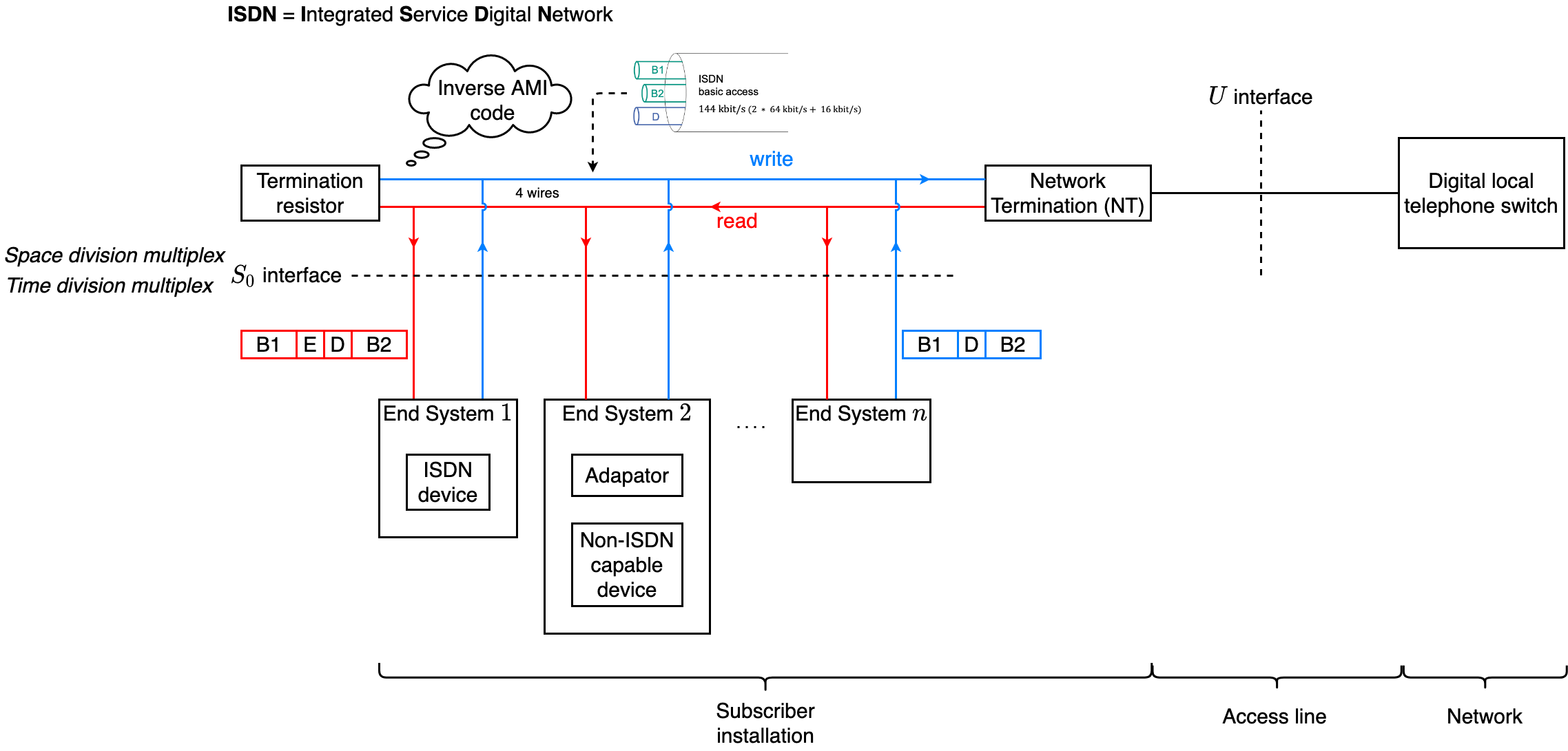
ISDN summary
ISDN = Integrated Services Digital Network
- 🎯 Goals
- Digital up to the subscriber
- Integration of different services (e.g., voice, data, images)
- Offering additional services
- Redialing
- Direct call
- Automatic call-back if receiver access is busy
- Re-direction of calls
- …
Architecture
Clear Separation of Access and Network
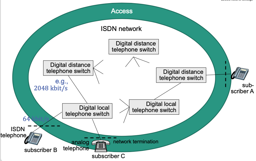
Example Topology
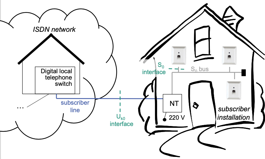
Simplified Architecture at Subscriber Interface
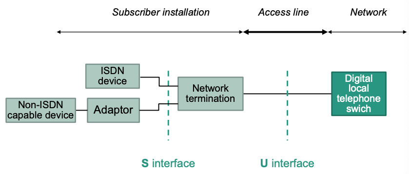
Network Termination (NT)
Termination of technical transmission
- Of network ( interface)
- Of subscriber installation ( interface)
Power supply for subscriber installation
Detect frame errors
Local telephone switch
- Media access to signaling channel (D channel, layer 2)
- Signaling at layer 3
- …
Adaptor: Provide ISDN functionality for non-ISDN capable device
ISDN Subscriber Interface
Basic access
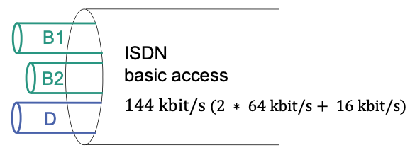
- 2 ∗ 64kbit/s+16kbit/s ()
- Two types of logical channels
- B channel: data transfer
- D channel: signaling traffic
B channel
- User data transmission
- Data rate: 64 kbit/s
- Two B channels available
- Operate independent of each other
- Can transmit in different directions
- Can transmit different data types (voice, images, …)
- Do not have to (but can) be active at the same time
- Medium access
- Fixed
- Time slots are associated with either B channel
D Channels
- Signaling (establish B channel between end systems)
- Data rate: 16 kbit/s
- Bidirectional communication: end system <–> network termination
- Medium access
E(cho) channel
- Data rate: 16 kbit/s
- Unidirectional communication: network termination –> end system
- Required for medium access
- Carrier sensing (CS)
- Collision detection (CD)
Channels and Layering
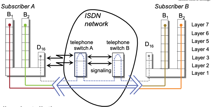
- Subscriber installation
- B channels
- Layer 1 standardized
- Layers 2-7 usage dependent
- D channel: Layers 1-3 standardized
- B channels
Subscriber Interface
Subscriber Interface
Four-wire transmission
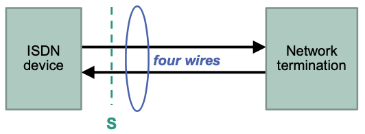
- One twin conductor per direction
- Simplex operation, both directions separated
Multiplexing at interface
- Space division multiplex: Separation of directions
- Time division multiplex: Frame structure ( frames)
Bus Topology at Interface
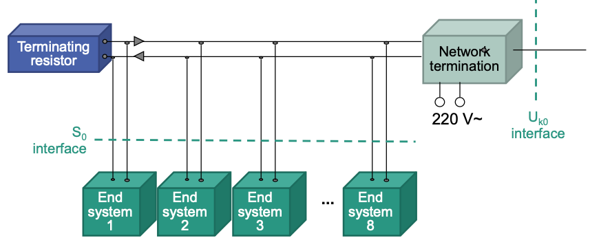
- Each end system has two connections to the bus
- In direction to network termination: write access
- In direction to end system: read access
Frames
Time division multiplex in both directions
End system –> network termination

End system <– network termination

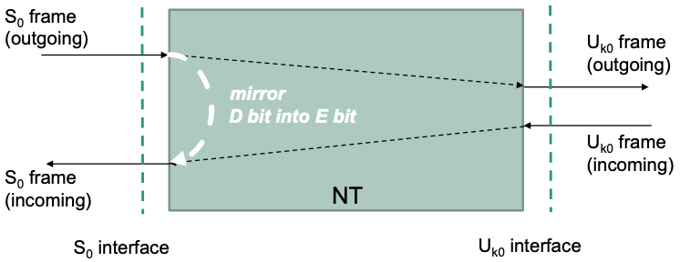
NT mirrors D channel into echo channel of incoming frames
Channel Encoding
Inverse AMI code (0 “overwrites” 1)
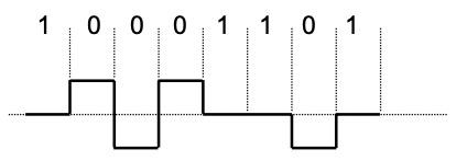
- 0: alternating by positive or negative level over whole tact interval
- 1: represented by 0 level
D Channel: Medium Access
Systems access D channel independent of each other
- E.g., to establish a connection
CSMA/CD based approach
Check medium (echo channel as mirror of D channel)
Free, when there is no activity visible for a duration of 8 bit
Protocol on layer 2 in D channel is variant of HDLC
Format of an HDLC frame

Delimited by flag (
01111110)Bit stuffing to conserve data transparency for higher layers

- After 5 subsequent binary “1” sender adds a binary “0”
- This happens inbetween the flags
- After 5 subsequent binary “1” receiver removes a following binary “0”
- Bit stuffing is done when sending the bit stream
- Calculate checksum before bit stuffing
- “Inversed” bit stuffing when receiving bit stream
- Verify checksum after “inversed” bit stuffing
- After 5 subsequent binary “1” sender adds a binary “0”
8 bit no activity on D channel represents 8 ones (inverse AMI-code)
Send: 1-persistent
Collision detection through sending system
- Systems listen on E channel while sending
- Other signal received on E channel than send on D channel?
- 0 overwrites 1
- Detecting system aborts sending and continues to check medium
- No further bit is send on D channel
- No exponential backoff
- Other system does not note anything and continues sending successfully
DSL
DSL = Digital Subscriber Line
🎯 Goal
- Performant solution for subscriber connection
- Support data services with higher data rates
“Invariant”: Twin conductor at the U interface = connection to customer premise
Categories
ADSL (Asymmetric DSL)
Follows the typical communication model of the WWW
A lot of data is received from the server
Much less own data is send to the server
Downstream and upstream data rates are asymmetric
- Downstream (From server to subscriber): 768 kbit/s – 8 Mbit/s
- Upstream (From subscriber to server): 128 kbit/s – 576 kbit/s
Subscriber connection
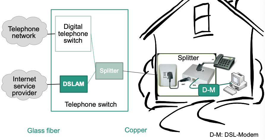
- Splitter
- Separates signal in telephone and data signal
- Required at subscriber as well as in telephone switch
- Works passive: Telephone signal stays available even when splitter fails
- Copper twin conductor
- Between splitters at subscriber and telephone switch
- DSLAM
DSL Access Multiplexer
Counterpart to DSL modem at subscriber
- Splitter
SDSL (Symmetric DSL)
- Mainly used by business customers
- Most often much more expensive than ADSL
- Only data, i.e., no parallel phone calls possible
Data Transmission at DSL Access
Frequency Multiplexing
Different frequencies for
- Telephony
- DSL upstream
- DSL downstream

Sources of Signal Disturbance
Damping: primary influenced by three parameters
- Distance, interference, cable diameter
Damping decreases with increasing cable diameter
–> Larger diameter permits higher data rates on same distance
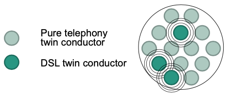
Crosstalk
- Interference between sender and receiver
- Interference between senders –> Only some twin conductors of a cable bundle can be used for ADSL
ADSL2, VDSL2
DSL Access Network
Basic configuration
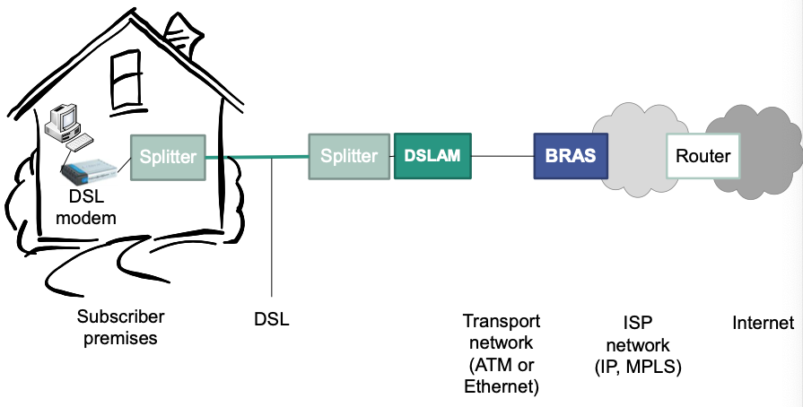
- BRAS: Broadband Remote Access Server
- Part of the ISPs core network
- Tasks
Routes traffic to/from broadband access devices (e.g., DSLAM)
Aggregates traffic of multiple DSLAMs
Can support policy management, quality-of-service
Provides layer-2-connectivity
Provide layer-3-connectivity
Interfaces to AAA (Authentication, Authorization, Accounting)
Assigns IP addresses to clients
Setting up an ADSL Connection
Provider is at the same time network provider: Use PPP (point-to-point protocol)
- Establish phase –> LCP (link control protocol)
Setup PPP connection
Negotiate connection parameters
- Data rate, used carriers
Negotiate authentication method
Negotiate the Data Rate
- Fixed rate
- Data rate is set to fixed value
- Contains “safety margin”
- Adaptive rate
- Negotiate the maximum reachable data rate
- Fixed rate
- Authentication phase
- Authentication based on negotiated method
- Network phase
- Assignment of IP address
- Announcing address of the DNS server
Provider uses DSL resale link

- Sequence
- Abort previous sequence in the authentication phase
- Only at this time it is known that subscriber is customer of different provider
- Thereafter
- Forwarding all data to other provider
- Restart complete sequence
- Abort previous sequence in the authentication phase
Further Access Technologies
Cable TV Network
Initially only designed for TV and broadcast transmission
Today also useable for telephony and Internet
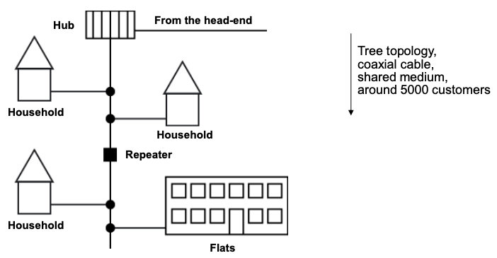
Topology
- Initially pure tree topology with coaxial cables
- Today combination of glass fiber and coaxial cables
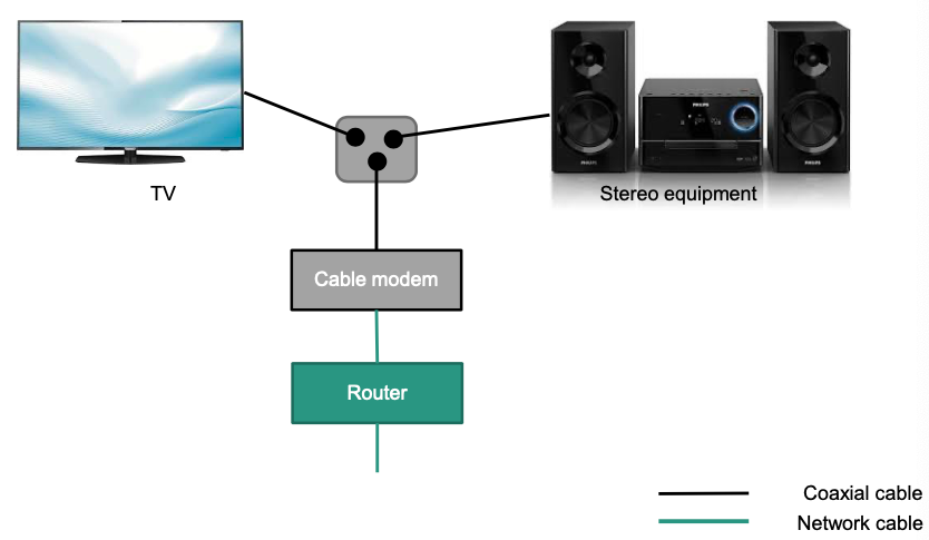
Configuration at household
Architecture
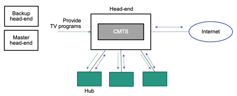
- CMTS: Cable Modem Termination System
From hub to households
Data transfer
- Downstream
- Broadcast: all subscribers receive same signal
- Cable modem filters out “own” packets
- Upstream
- Access to channels controlled by time multiplex (time slots)
- Time slots are assigned by CMTS in the head-end
- Shared medium: Reachable data rate depends on number of concurrent users
- Downstream