Ethernet Basics
CSMA/CD
CSMA/CD = Carrier Sense Multiple Access with Collision Detection
- Media access control method used in early Ethernet technology
Carrier Sense Multiple Access
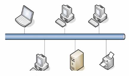
Carrier: transmission medium that carries data, e.g.
Electronic bus in Ethernet network
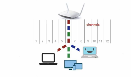
Band of the electronmagnetic spectrum (channel) in Wi-Fi network
Carrier Sense
A node (i.e. Network Interface Card, NIC) on a network has a sense: it can listen and hear. It can detect what is going on over the transmission medium.
Multiple Access
Every node in the network has equal right to access to and use the shared medium, but they must take turns
Putting them together, CSMA means Before a node transmits data, it checks or listens to the medium
- Medium not busy ➡️ the node sends its data
- When the node detects the medium is used ➡️ It will back off and wait for a random amount of time and try again
Collision Detection: A node can hear collision if it happens
Example
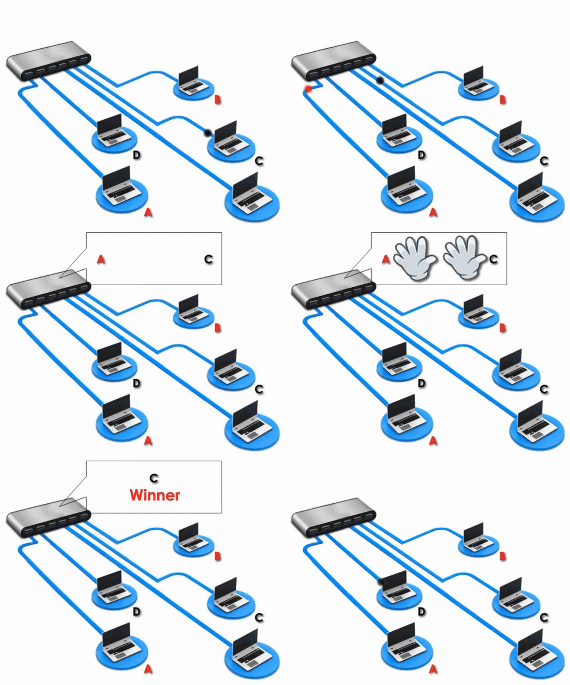
Both A and C want to transmit their data. They check the media and find it is not busy. So they send their message at the same time. Collision occurs. When these two nodes hear the collision, they will back off and use some kind of randomization to decide which would go first in order to avoid collision.
Ethernet Frame
Frame = a protocol data unit (PDU)
PDU in different layer of the OSI model is named differently.
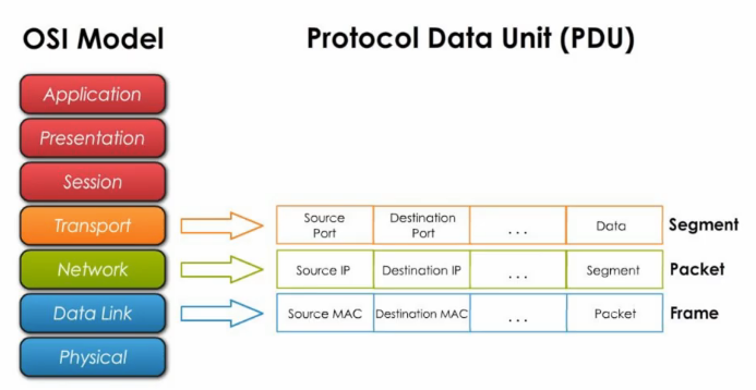
Among the Ethernet family, frames can be different. For any two devices to communicate, they must have the same type of frames.
An Ethernet frames has seven main parts:

Preamble
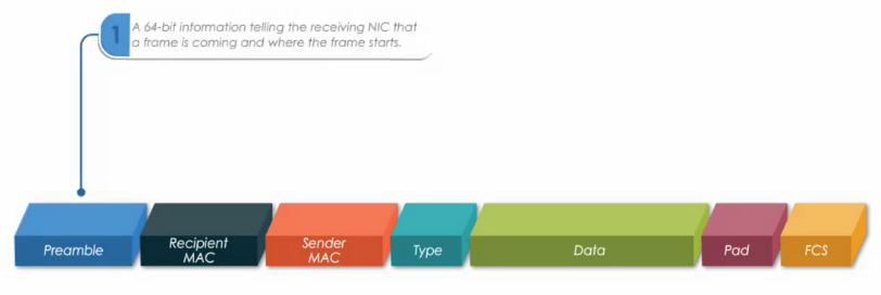
A 64 bit header information telling the receiving node that a frame is coming and where the frame starts
Recipient MAC
Recipient’s MAC address
Sender MAc
Sender’s MAC address
Type
Tells the recipient the basic type of data, such as IPv4 or IPv6
Data
- Payload carried by frame, such as IP packet from Network layer.
- Limit is 1500 Bytes
Pad
Extra bits to make a frame at least bigger than 64 Bytes (Any data unit < 64 Bytes would be considered as collisions)
FCS = Frame Check Sequence
Used for error checking and the integrity verfication of a frame
Spanning Tree Protocol (STP)
Complete Graph and Spanning Tree
Complete Graph
A graph in which each pair of graph vertices is connected by a line
- I.e., when all the points are connected by the maximum number of lines, we get a complete graph
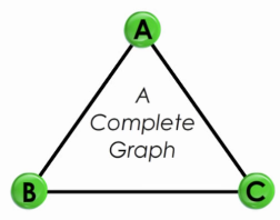
In networking field, a complete graph is like a fully meshed network
Spanning tree
- All points are connected by a minimum number of lines
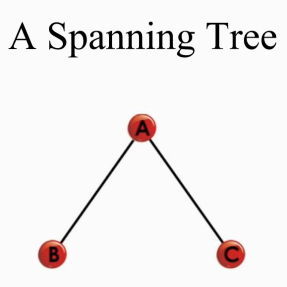
From the complete graph above, we can get three spanning trees:
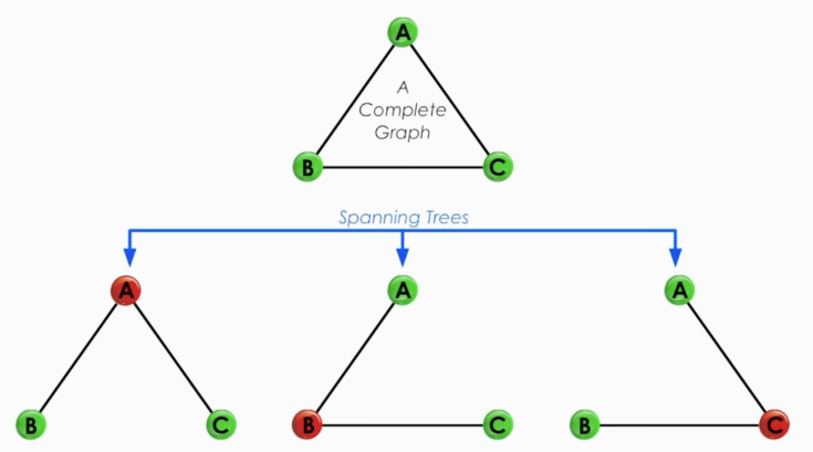
All three points are connected and no loop is formed.
Basic features
- NO loop
- Minimumly connected (i.e., removing one line will leave some point disconnected)
Spanning Tree Protocol
Spanning Tree Protocol (STP)
Layer 2 protocol that runs on bridges and switches and builds a loop-free logical topology.
🎯 Main purpose: eliminate loops
Three basic steps:
- Select one switch as root bridge (central point on the network)
- Choose the shortest path (the least cost) from a switch to the root bridge
- Path cost is calculated based on link bandwidth: the higher bandwidth, the lower the path cost.
- Block links that cause loops while maintaining these links as backups
Example
Suppose we have a simple network
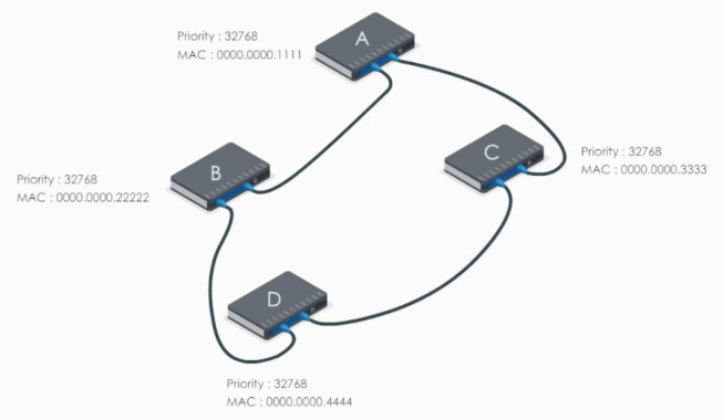
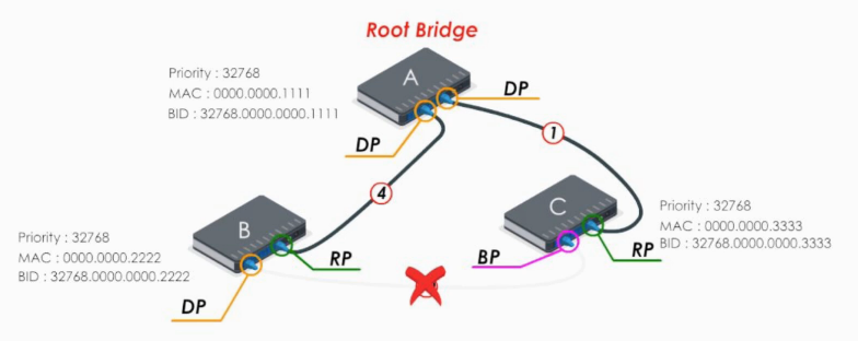
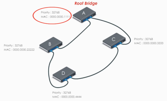
First, STP elects the root bridge. The lowest bridge ID (priority: MAC address) determins the root bridge. Here swithc A is elected as the root bridge.
Next each of other switches chooses the path to the root bridge with least path cost. Here we just skip the details of calculation and mark the path cost for each link.
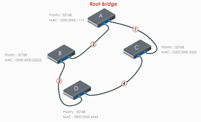
Now let’s take a look at switch B. For switch B, there’re two paths to reach root bridge, switch A:
- BDCA: costs 7 (2 + 4 + 1)
- BA: costs 2
Therefore, the link BA is chosen as the path from switch B to root bridge A.
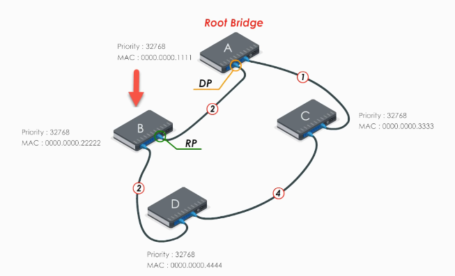
- RP: Root port, the port with the least cost path to the root bridge
- DP: designated port.
For switch C and D, the procedure is similar.
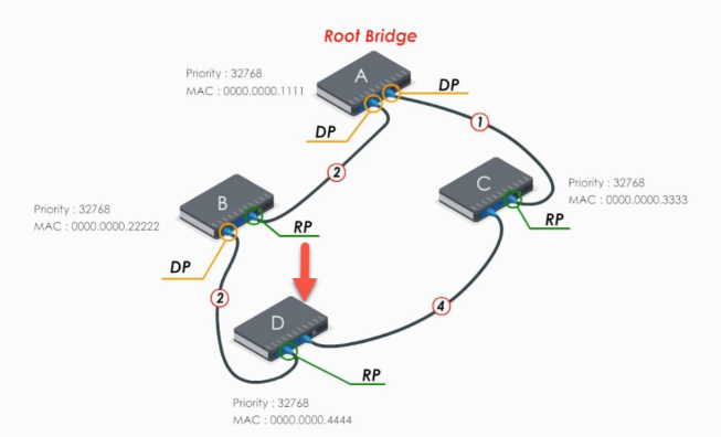
Note
A non-root switch can have many designated ports, but it can have only ONE root port.
All ports of the root bridge are designated ports. On the root bridge, there is NO root port.
Now every switch has found the best path to reach the root bridge. And the links between D and C should be blocked in order to eliminate a loop.
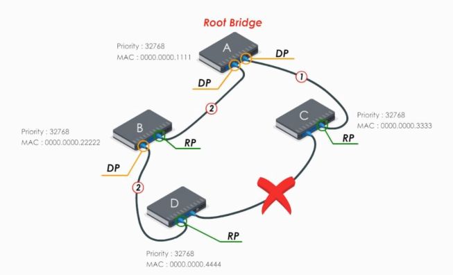
Let’s look at the blocked link DC
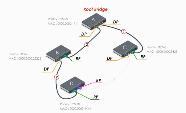
The port with the lowest switch ID would be selected as the designated port. The other end is blocking port. The blocking port can still receive frames, but it will not forward or send frames. It simply drops them.
How STP Elects Root Bridge?
Root bridge election is based on a 8 byte switch Bridge ID (BID)
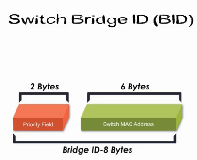
- 2 Bytes Priority Field
- 6 Bytes Switch MAC address
Root bridge election process is simple: All interconnected switches exchange their BIDs
- Whoever has the lowest priority field value would become the root bridge
- If priority filed is equal, whoever has the lowest MAC address would become the root bridge
BPDU
Every switch multicasts its message, Hello BPDU, in which each swich declares ifself the root bridge.
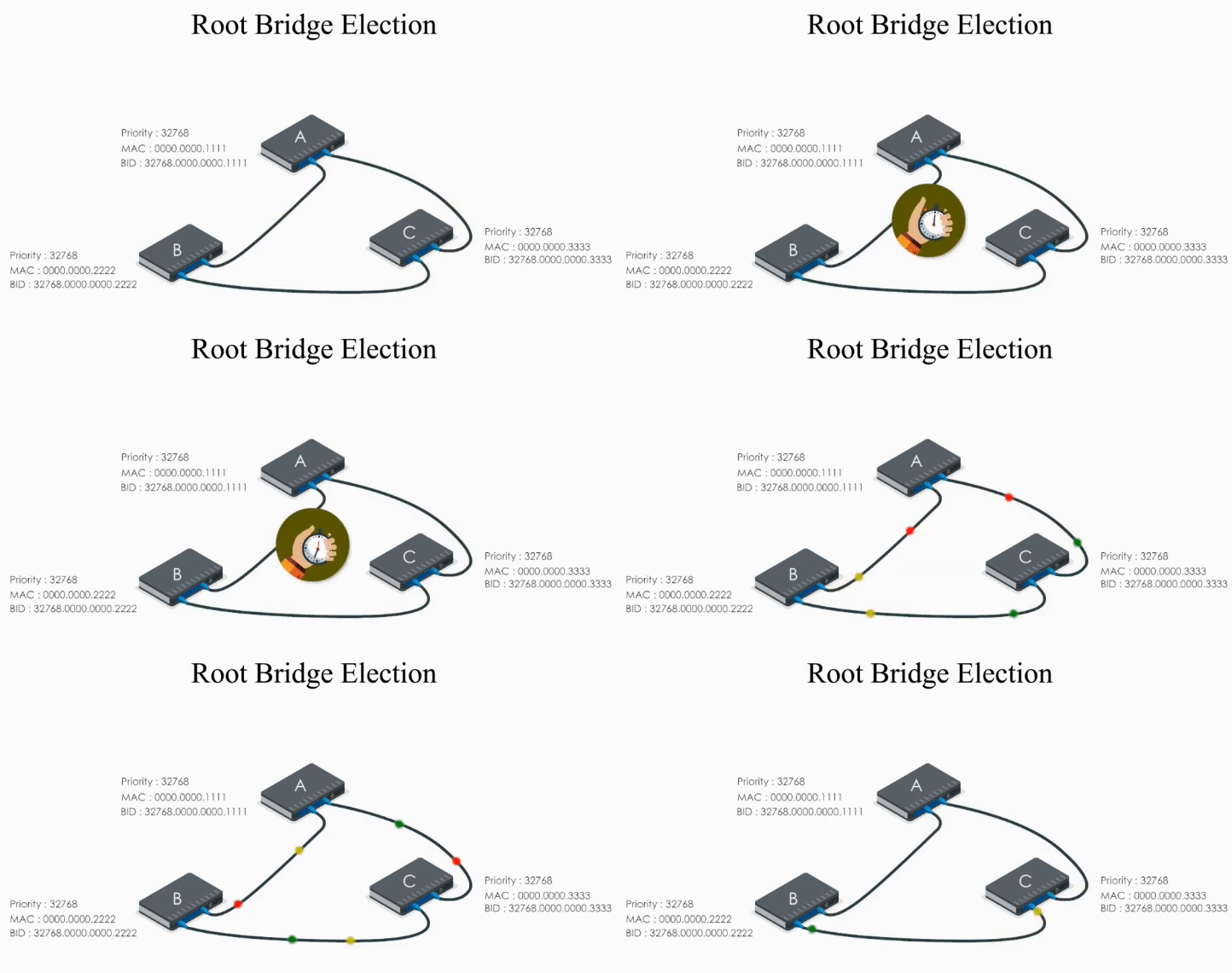
Bridge Protocol Data Unit (BPDU) is a frame containing information about spanning ree protocol.
Hello BPDU is used by switches or bridges to share information about themselves. It is used for
- electing a root bridge
- determining ports roles and states
- blocking unwanted links
In other words, Hello BPDU is used to configure a loop-free network.
Structure of BPDU:
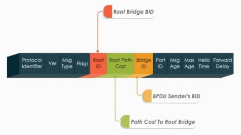
Three important fields:
- Root ID: Root Bridge BID
- Root Path cost: The best path cost to the root bridges
- Bridge ID: BPDU sender’s ID (Source BID)
The Election Process
One thing need to be kept in mind: Each port of a switch is uniquely identified.
Consider the example above:
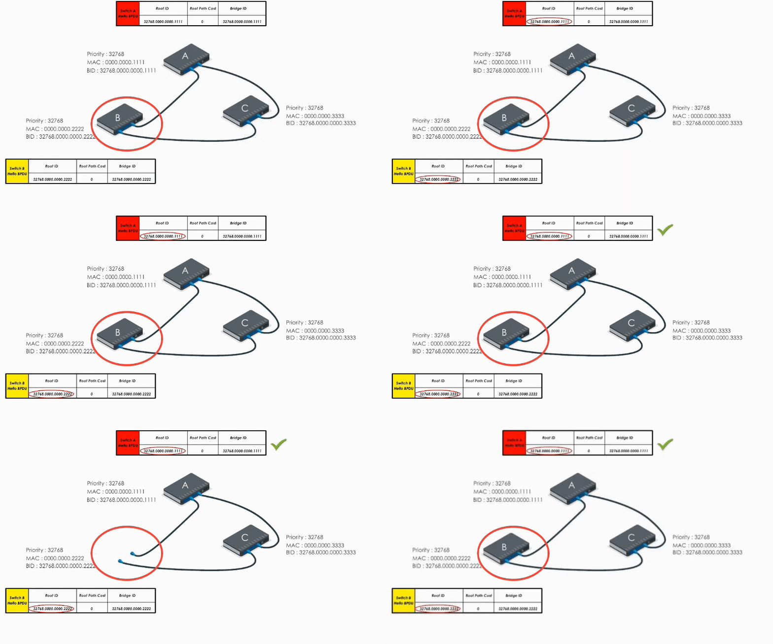
Switch A, B, and C send out their Hello BPDUs. Basically each switch declares itself the root bridge.

Let’s take a look at Switch A first.
Switch A sends out its Hello BPDU to B and C
- Switch A sets it Root ID to its own BID (“Hello everyone, I am the root bridge”)
- Path cost value is set to 0
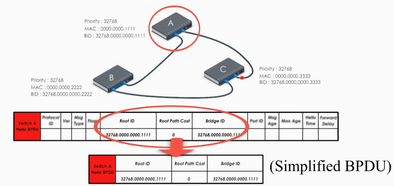
Switch B and C do the same thing.
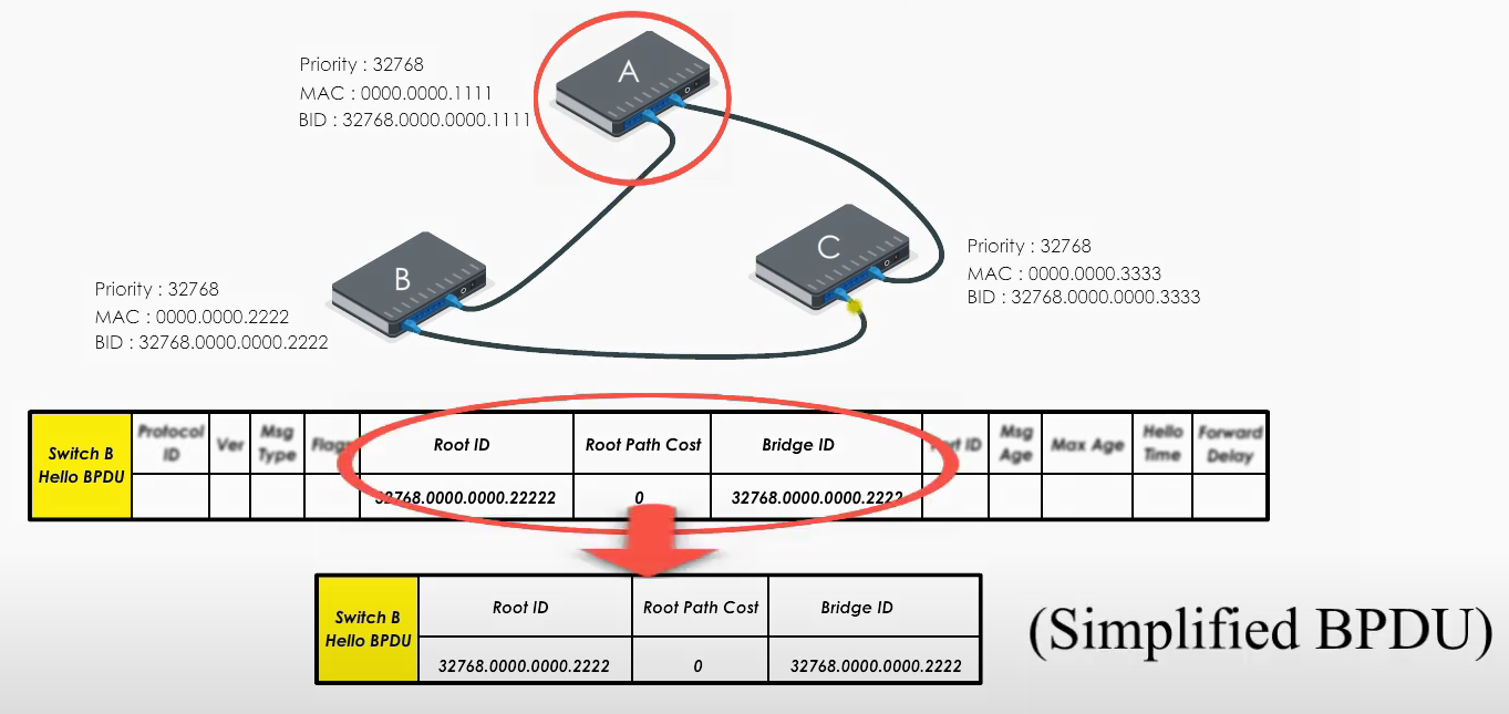
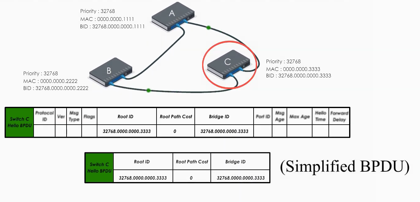
Basically they all claim they are the root bridge (“the boss”) in their Hello BPDUs.
The problem is: ONLY one can be the root bridge.
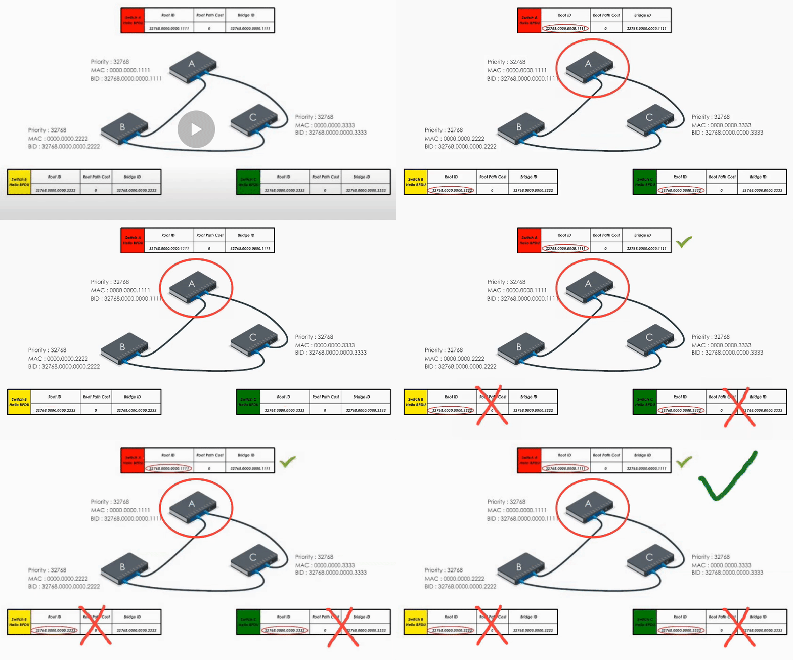
What they do next is to compare their Hello BPDUs and to elect a real boss.
When Switch A receives Hello BPDUs from B and C, it checks and discards their BPDUs because its bridge ID is lower than B’s and C’s. So A keeps its original Hello BPDU and still believes it is the root bridge.
When Switch B receives the Hello BPDU from C, it compares and finds its Bridge ID is lower (i.e. B’s BPDU is superior) thus discards C’s Hello BPDU
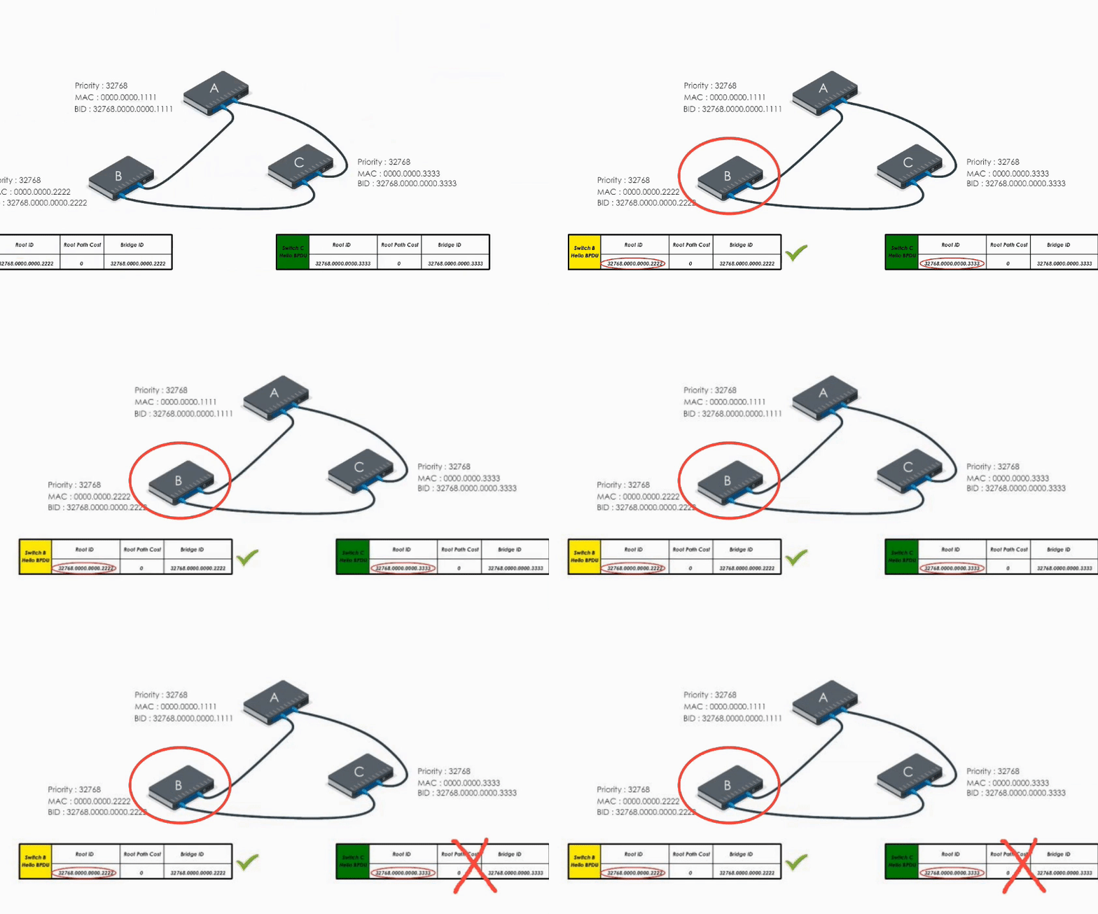
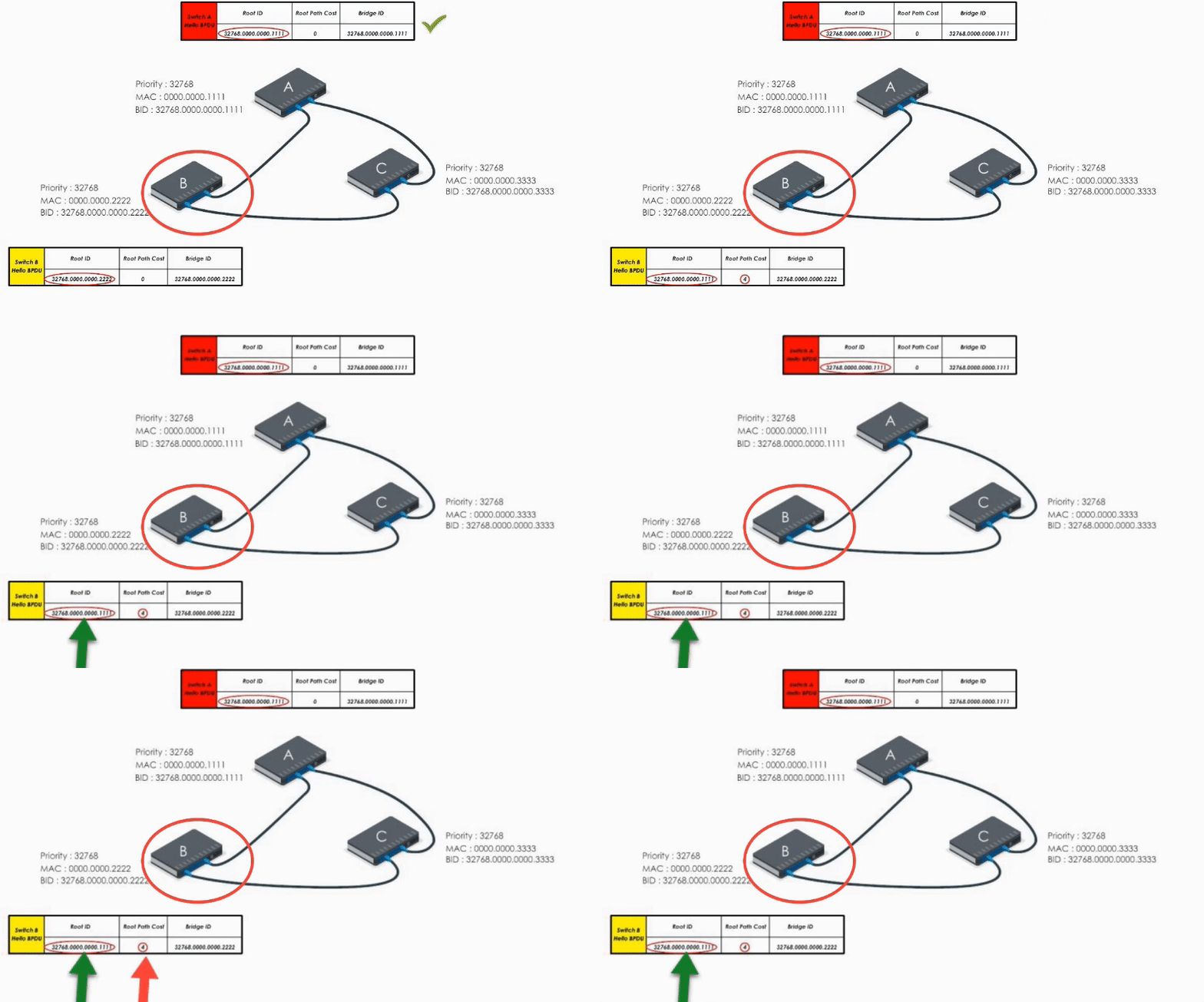
When B receives A’s Hello BPDU, it finds A’s Bridge ID is lower. It would say “Well, Switch A is the winner”.
Therefore, it modifies its Root ID value by replacing its own bridge ID with Switch A’s bridge Id. It also calculates the path cost to switch A (let’s say 4), and then sends the modified Hello BPDU to others.
When Switch C receives Hello BPDU from A and B, C finds A’s is a superior BPDU. So C changes the value of the root ID to switch A’s Bridge ID. And it calculates the path cost to switch A (let’s say 1). Then it sends its modified Hello BPDU to others.
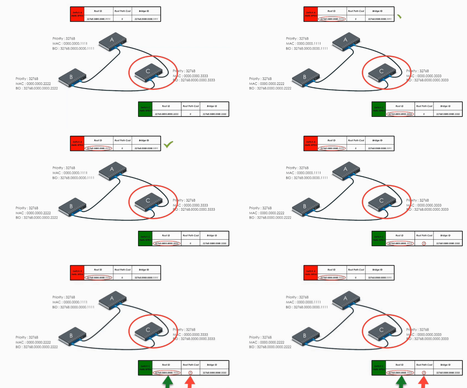
This way, A, B, and C exchange their BPDUs again and agree that the root bridge should be switch A.
Once the root bridge is decided, path cost to the root bridges are calculated. Root ports, designated ports, and blocked ports are determined. STP has created a loop-free network! 👏
