Router
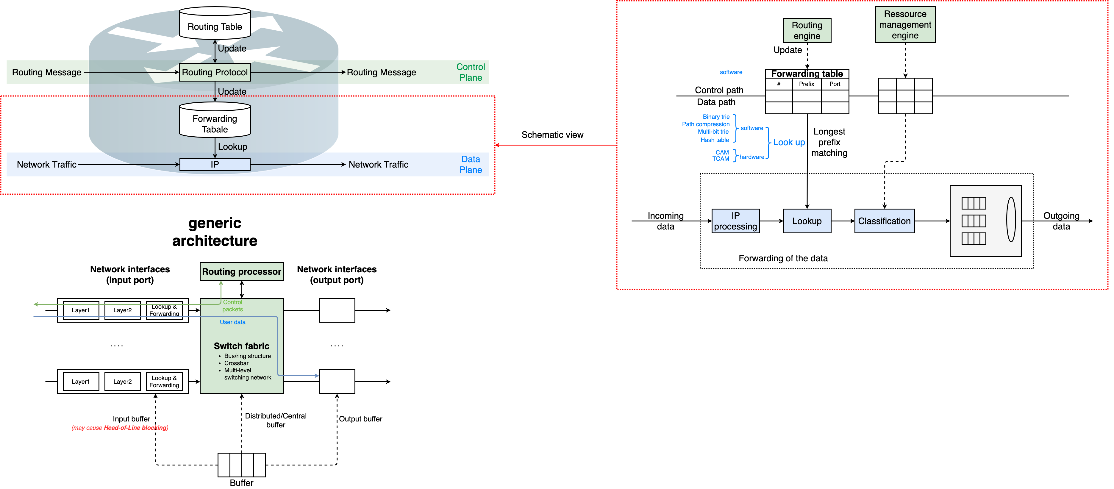
Schematic view and generic architecture of router
Basic Functionalities
Intermediate Systems
Forward data from input port(s) to output port(s)
Forwarding is a task of the data path
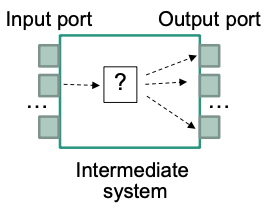
May operate on different layers
- Hubs operate on layer 1
- Bridges operate on layer 2
- Routers operate on layer 3
Routing
Determines the path that the packets follow
Routing is part of the control path Requires routing algorithms and routing protocols
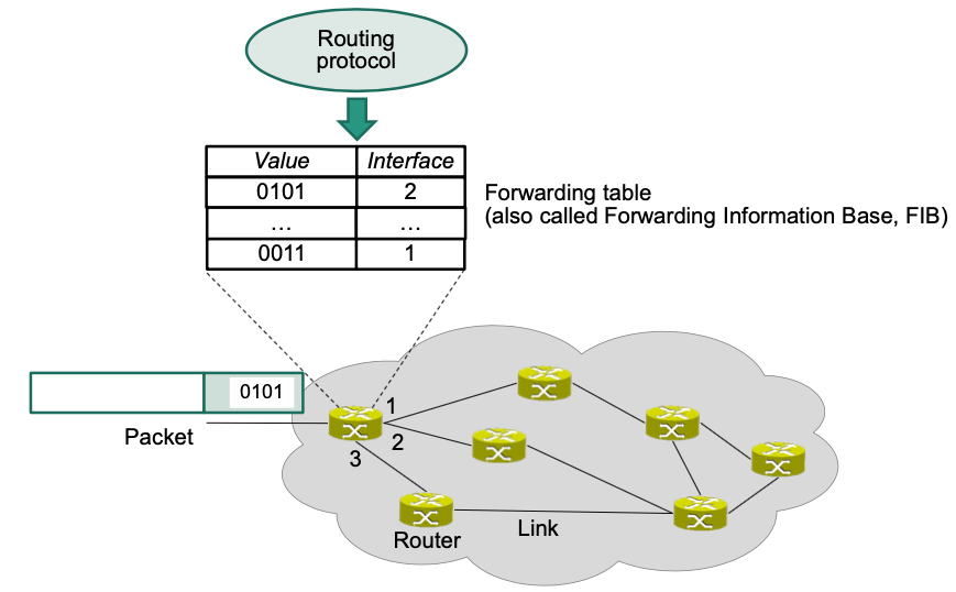
Forwarding within a Router
Main task
- Lookup in forwarding table
- Forward data from input port to output port(s)
🎯 Goals
- Forwarding in line speed
- Short queues
- Small tables
Schematic View of an IP-Router:
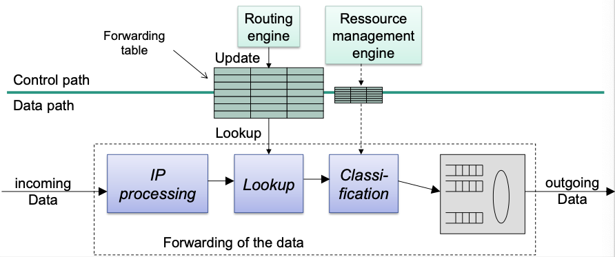
Forwarding Functionality
Basic functions
- Check the headers of an IP packet
- Version number
- Valid header length
- Checksum
- Check time to live
- Decrement of TTL field
- Recalculate checksum
- Lookup
- Determine output port for a packet
- Fragmentation
- Handle IP options
Possibly: differentiated treatment of packets
- Classification
- Prioritization
Challenge: Line Speed
- Bandwidth demand increases
- Link capacity has to increase as well to keep up
Types of Routers
Core router
- Used by service providers
- Need to handle large amounts of aggregated traffic
- High speed and reliability essential
Fast lookup and forwarding needed
Redundancy to increase reliability (dual power supply …)
- Cost secondary issue
Enterprise router
Connect end systems in companies, universities …
Provide connectivity to large number of end systems
Support of VLANs, firewalls …
Low cost per port, large number of ports, ease of maintenance
Edge router (access router)
At edge of service provider
Provide connectivity to customer from home, small businesses
Support for PPTP, IPsec, VPNs …
Forwarding Table Lookup
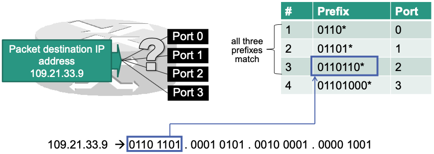
Example of a forwarding table

Prefix
- Identifies a block of addresses
- Continuous blocks of addresses per output port are beneficial
- Does not require a separate entry for each IP address Scalability 👏
Longest Prefix Matching
- Consider a typical problem: What to do if there are multiple prefixes in the forwarding table that match on a given destination address?
- 🔧 Solution: Select most specific prefix
- most specific prefix = the longest prefix
- Example
Efficient Prefix Search
Different approaches for fast prefix search (in software)
Efficient data structures
Requirements
- Fast lookup
- Low memory
- Fast updates
Naïve approach: Simple Array
Variables
- = number of prefixes
- = length of a prefix (e.g., for full IPv4 addresses)
- = length of a stride (only for multibit tries)
How it works?
Store prefixes in a simple array (unordered)
Linear search
Remember best match while walking through array
Evaluation
- Worst case lookup speed: pretty bad 🤪
- Memory requirement: pretty bad 🤪
- Updates:
Binary Trie
Tries tree-based data structures to store and search prefix information
- From „retrieval“ (find something)
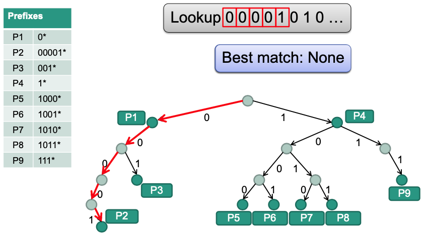
💡 Idea: Bits in the prefix tell the algorithms what branch to take
Example
Evaluation
- Worst case lookup speed:
- Maximum of one node per bit in the prefix
- But much better than naïve approach ()
- Memory requirement:
- Assumption: prefixes stored as linked list starting from root node
- Every prefix (out of ) can have up to nodes Maximum of entries
- No improvement (compared with naïve approach) 🤪
- Updates:
- A maximum of nodes has to be inserted or deleted (similar to lookup procedure)
- Worst case lookup speed:
Performance
Can find prefix in steps address space =
- number of bits in address ( for IPv4, for IPv6)
Assumption: separate memory access required for each step
Memory access time
Maximum lookups per second:
For 100 byte packets, this results in only Gbit/s
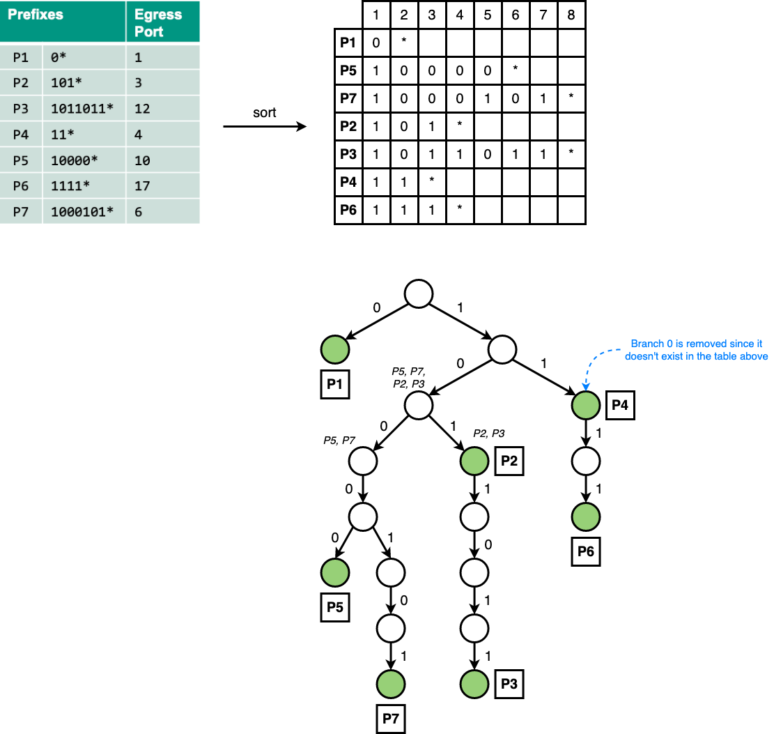
Example
Construct binary trie
Optimization
Path Compression
Long sequences of one-child nodes waste memory
E.g. highlighted (red) search paths in following trie is not required for branching decision
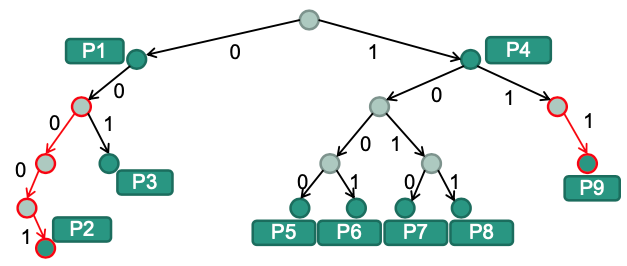
💡 Idea: Eliminate those sequences from trie
Lookup operation
Additional information required
Store bit index that has to be examined next
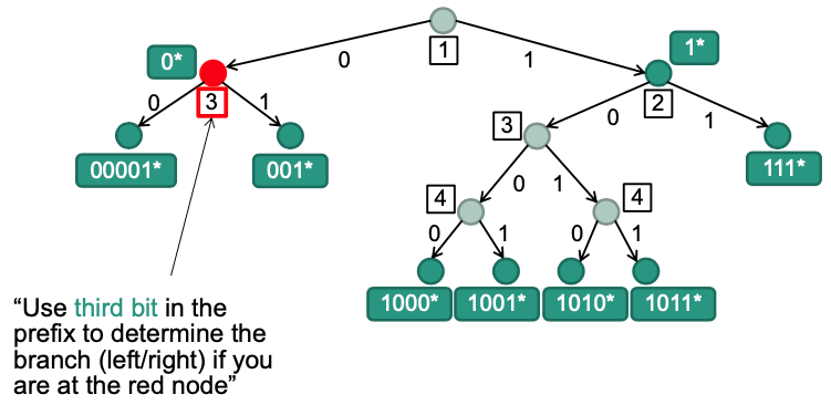
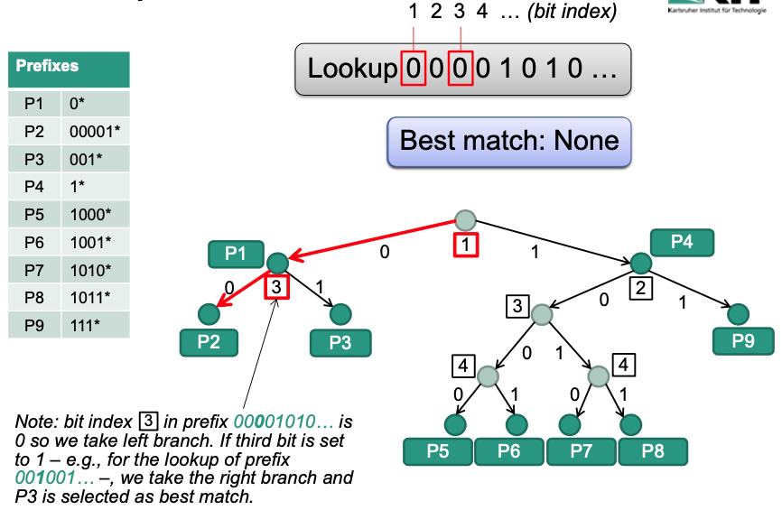
Evaluation
Worst case lookup speed:
If there are no one-child nodes on a path, number of nodes to search is equal to length of prefix
Memory requirement:
Maximum of leaf nodes, for the internal nodes
Maximum of entries
Improvement against binary trie 👏
Updates:
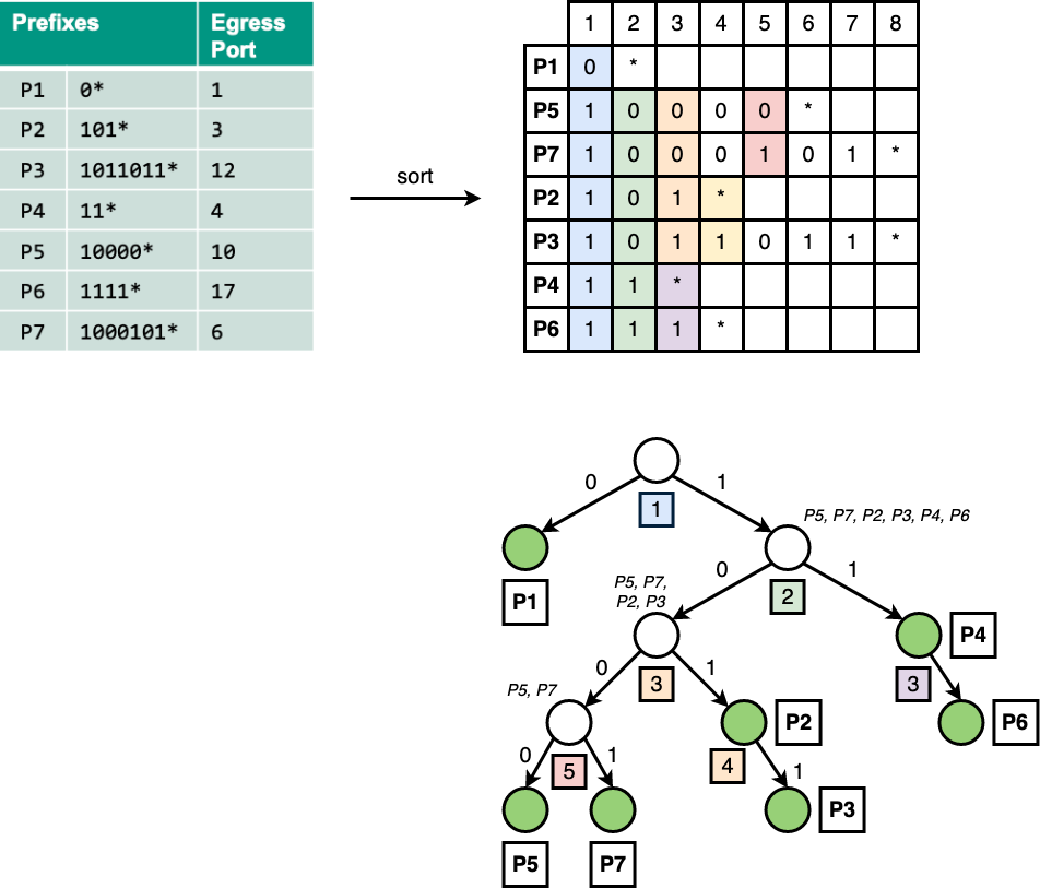
Example
Construct binary trie with path compression
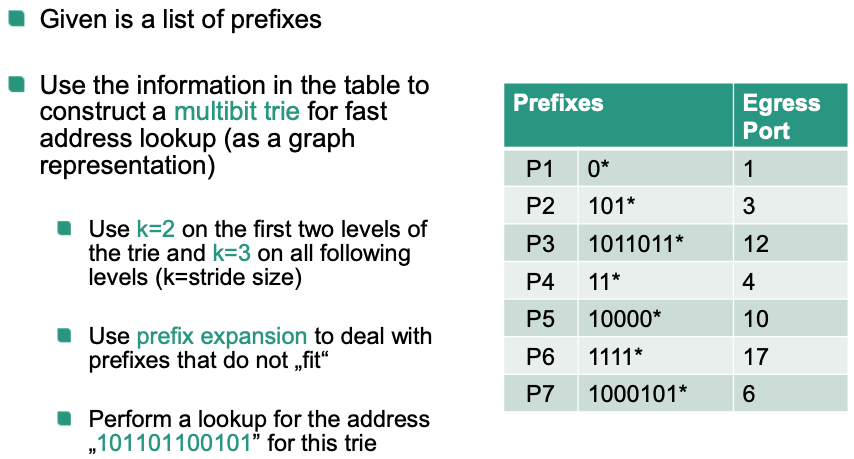
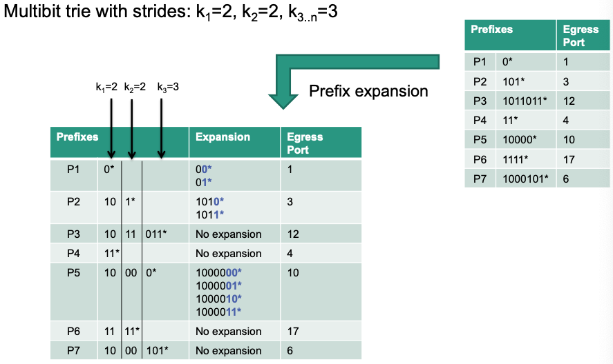
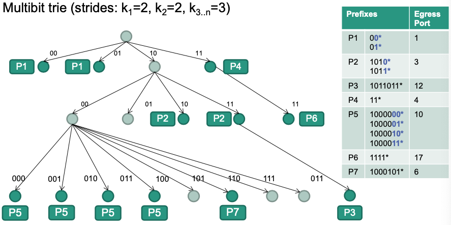
Multibit Trie
Example: Homework 03
Hash Tables
- 🎯 Obejctives
Improve lookup speed
Hash tables can perform lookup in
However: longest prefix match only with hash table doesn‘t work 🤪
- Instead: use an additional hash table
- Stores results of trie lookups
- E.g., destination IP address 109.21.33.9 output port 2
- Significant improvement for large forwarding tables 👏
- Stores results of trie lookups
- For each received IP packet
- Does an entry for destination IP address exist in hash table?
- Yes no trie lookup
- No trie lookup
- Works well if addresses show „locality“ characteristics
- I.e., most IP packets are covered by a small set of prefixes
- Not applicable in the Internet backbone
- Does an entry for destination IP address exist in hash table?
Comparsion between Binary Trie, Path Compression, and Multibit Trie
- = number of prefixes
- = length of a prefix (e.g., for full IPv4 addresses)
- = length of a stride (only for multibit tries)
| Lookup Speed | Memory Requirement | Update | |
|---|---|---|---|
| Binary trie | |||
| Path compression | |||
| Multibit trie |
Longest Prefix Matching in Hardware
RAM-based Access
- 💡Basic idea
- Read information with a single memory access
- Use destination IP address as RAM address
- 🔴 Problem
- Independent of number of prefixes in use
- IPv4 addresses with length of 32 bit requires 4 GByte
- IPv6 addresses with length of 128 bit requires ~ GByte
- Waste of memory
- Required memory size grows exponentially with size of address!
- Independent of number of prefixes in use
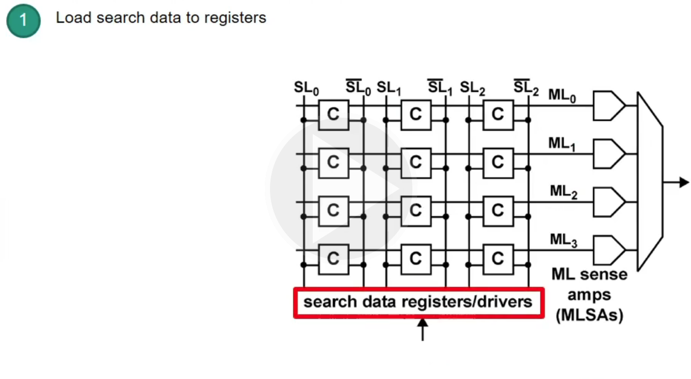
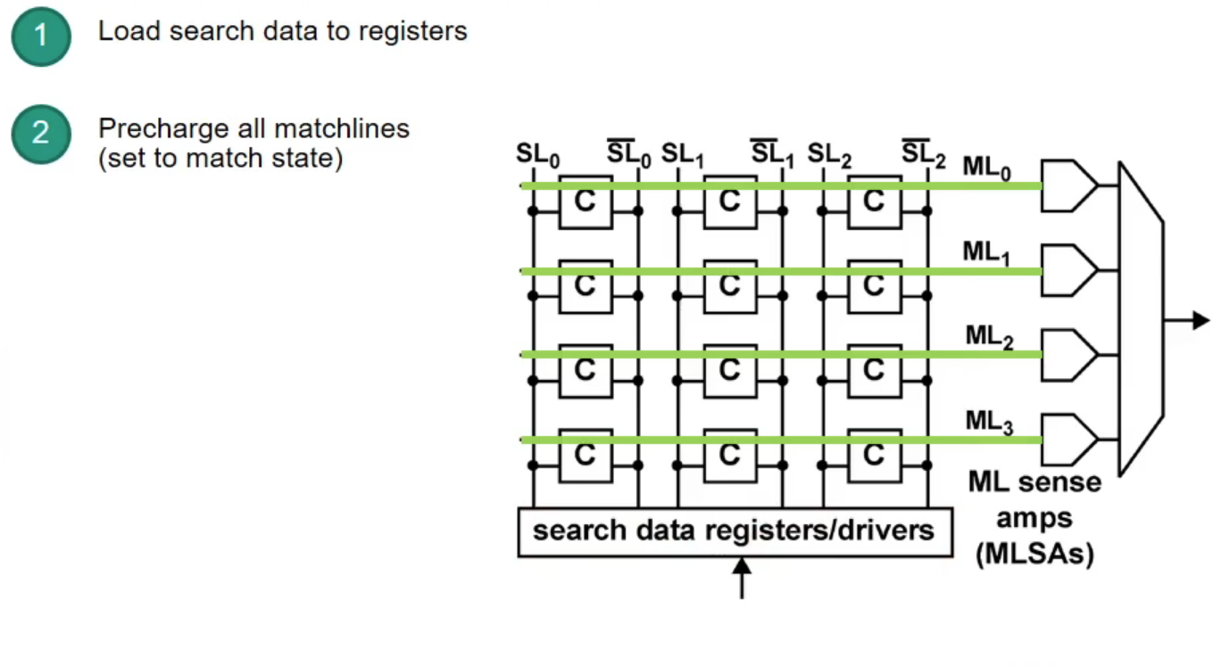
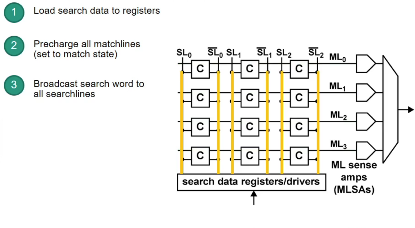
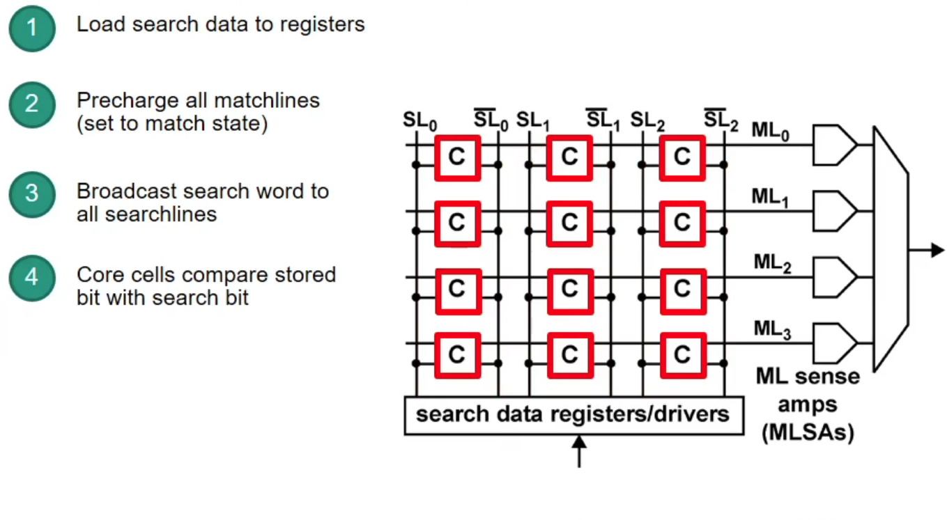
Content-Addressable Memory (CAM)
CAM: takes data and returns address (opposite to RAM)
- CAM can search all stored entries in a single clock cycle (very fast!)
- Application for networking: use addresses as search input to perform very fast address lookups (IP output port)
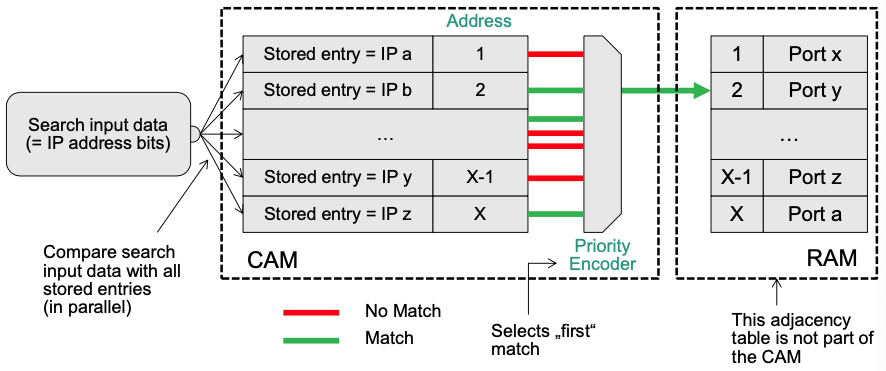
Structure of CAM
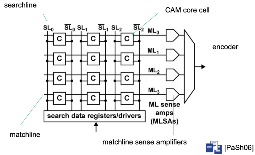
How does CAM work?
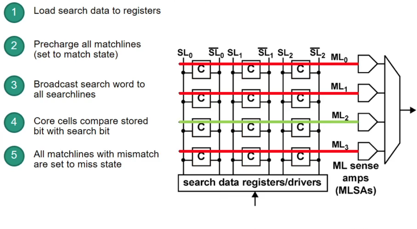
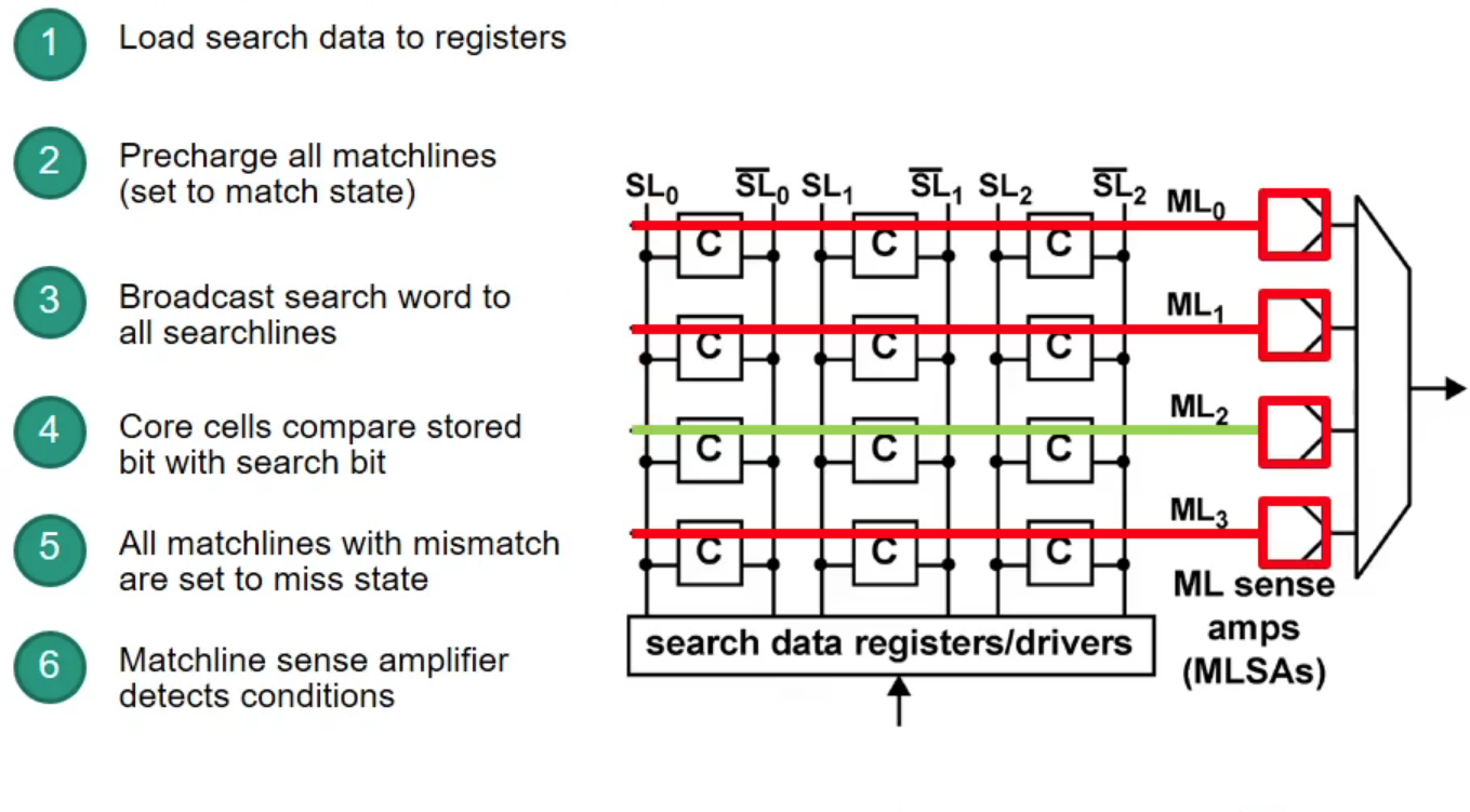
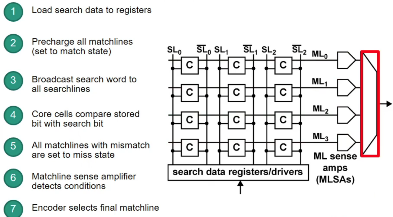
Example

Source: [Content-Addressable Memory Introduction](https://www.pagiamtzis.com/cam/camintro/)
Ternary CAM (TCAM)
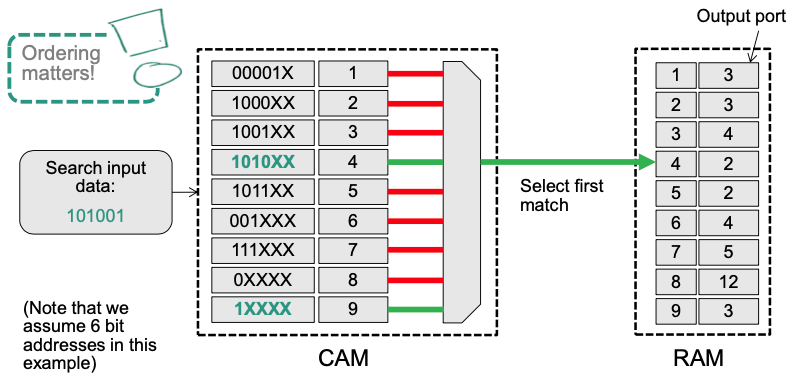
- An extension that supports a „Don‘t Care“ State x (matching both a 0 and a 1 in that position)
- Allows longest prefix matching
- Prefixes are stored in the CAM sorted by prefix length (from long to short)
- 👍 Advantage: Very fast lookups (1 clock cycle)
- 🔴 Problems: Severe scalability limitations
- High energy demand
- All search words are looked up in parallel
- Every core cell is required for every lookup
- High cost / low density
- TCAM requires 2-3 times the transistors compared to SRAM
- Longest matching prefix requires strict ordering of prefixes in the TCAM
- New entries can require the TCAM to be „re-ordered“ This can take a significant amount of time!
- High energy demand
Example: Homework 04
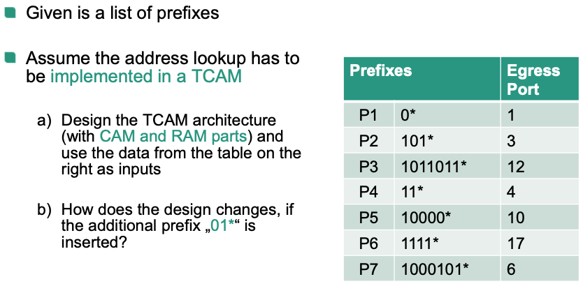
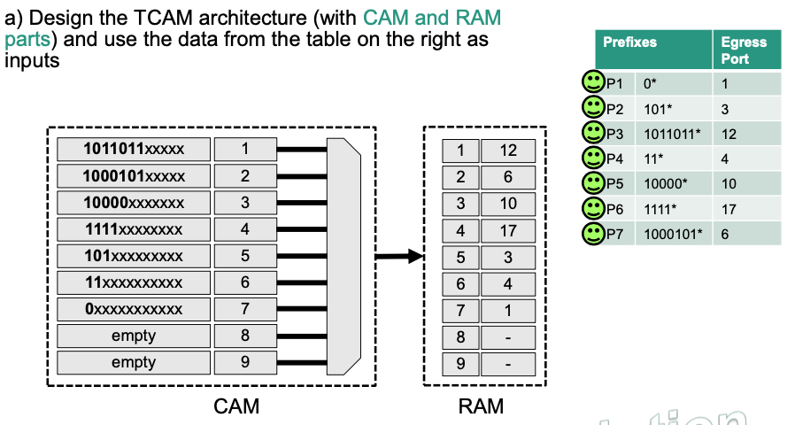
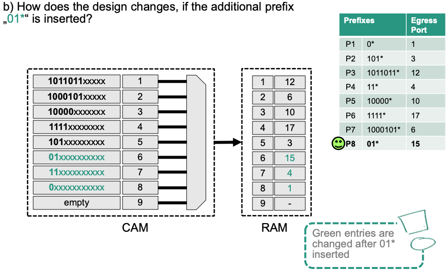
💡 Idea:
- Sort prefixes from according to their length (longest to shortest)
- CAM part: (prefix, index) pair
- RAM part: (index, egress port) pair
Router Architecture
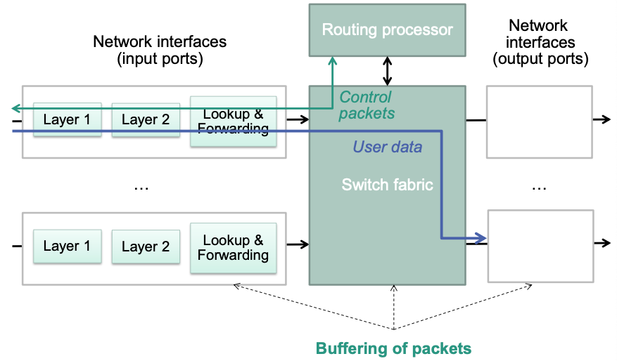
Basic components
- Network interfaces
- Realize access to one of the attached networks
- Functionalities of layers 1 and 2
- Basic functions of IP
- Including forwarding table lookup
- Routing processor
- Routing protocol
- Management functionality
- Switch fabric
- „Backplane“
- Realizes internal forwarding of packets from the input to the output port
Generic Router Architecture
Conflicting design goals
- High efficiency
- Line speed
- Low delay
- Vs. low cost
- Type and amount of required storage
- Type of switch fabric
- High efficiency
Blocking
E.g., packets arriving at the same time at different input ports that need the same output port
Measures that can help prevent blocking
Overprovisioning
Internal circuits in switch fabric operate at a higher speed than the individual input ports
Buffering
Queue packets at appropriate locations until resources are available At
network interfaces
In switch fabric
Backpressure
- Signal the overload back towards the input ports
- Input ports can then reduce load
Parallel switch fabrics
- Allows parallel transport of multiple packets to output ports
- Requires higher access speed at output ports
Buffers
Problem: Simultaneous arrival of multiple packets for an output port
- Sequential processing required, since packets can not be sent in parallel
- Packets have to be buffered
Example
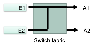
- Packets arrive at input ports E1 and E2 at the same time, both must be forwarded to output A1
- One out of the two packets requires buffering
Where to place the memory elements for buffering?
Evaluation of Alternatives
Parameters of switch fabric
- : Number of input and output ports
- : Total storage capacity
- : Speedup factor of the switch fabric
- According to the speed of the input and output ports
- : Cycle time of memory accesses
- According to the transmission time of a packet at input and output ports
- Delay und jitter (=variance of the delay)
Important
- Additional mechanisms are required, e.g. flow control
- Organization of memories, e.g. FIFO or RAM
In the following: simplifying assumptions
All ports operate at same data rate
All packets have same length
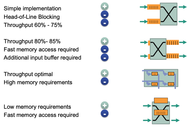
Input buffer
💡 Idea: conflict resolution at input of switch fabric
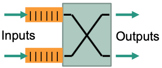
- FIFO buffer per input port
- Scheduling of inputs, e.g.
- Round robin, priority controlled, depending on buffer levels, …
- Jitter varies
- Switch fabric internally non-blocking, i.e., no internal conflicts 👏
Requirements
- Internal exchange with speed of connections ()
- Cycle time (One packet in, one packet out)
Characteristics
🔴 Problem: Head-of-Line blocking
Waiting packet at head of the buffer blocks packet behind it that could be serviced

Suppose that in the buffer of , the 1st packet are going to be sent to and the 2nd packet are going to be sent to . But currently the 1st packet is blocked. This caused that the 2nd packet can not be processed, although is not occupied. In other words, the 1st packet **blocks** the 2nd packet.
Maximum throughput is 75% for and 58,58% for
Output buffer
💡 Idea: conflict resolution at output of switch fabric
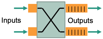
- FIFO buffer per output port
- Switch fabric internally non-blocking, i.e., no internal conflicts
Requirements
Internal switching of packets at times the speed of the input ports:
Switch fabric internally non-blocking
inputs must be processed at the same time (simultaneously)
Switching of packets during one cycle possible
In worst case, a buffer must take packets in and send one packet out.
Output buffer must be able to accept packets at times the speed
Input buffer necessary to accept a packet
Characteristics
- Maximum throughput near 100%, usually at approx. 80-85%
- Good behavior with respect to delay and jitter
Distributed buffer
💡 Idea: conflict resolution inside switch fabric
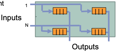
- Switch fabric as matrix
- FIFO buffer per crosspoint
Requirements
Matrix structure
Internal exchange with speed of connections:
Cycle time:
Characteristics
No Head-of-Line blocking 👏
Higher memory requirement than input or output buffering 🤪
Central buffer
💡 Idea: conflict resolution with shared buffer
All input and output ports are connected to a shared buffer (organization: RAM
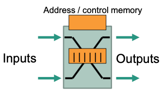
Requirements
- Cycle time
- Address and control memory for address information of packets and control of parallel memory accesses
Characteristics
Significantly lower memory requirements
But: requirements with respect to memory access time are higher 🤪
Buffer placement summary
Switch fabric
Four typical basic structures
Evaluation
The internal blocking behavior (Blocking / non-blocking)
The presence of buffers (Buffered / unbuffered)
Topology and number of levels of the switching network and number of possible routes
The control principle for packet routing (Self-controlling / table-controlled)
The internal connection concept (Connection oriented / connectionless)
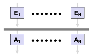
Bus or ring structure
💡 Idea
Conflict-free access through time-division multiplexing
Transmission capacity bus / ring
- At least the sum of the transmission capacities of all input ports
Characteristics
Easy support for multicast and broadcast
Spatial extension of a bus system is limited. Usually low number of connections (up to approx. 16)
Crossbar
💡 Idea: Each input connected to each output via crossbar
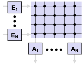
- inputs, outputs crosspoints
Characteristics
Partial parallel switching of packets possible
Multiple packets for the same output Blocking Buffering required
High wiring costs with a large number of inputs and outputs
- Mostly limited to 2x2 or 16x16 matrices
Especially efficient with packets of the same size
Multi-level Switching Networks
From the switching states of an elementary switching matrix

multilevel connection networks can be set up. E.g.,
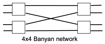
Characteristics
Less wiring effort than crossbar
Each input can be connected to each output
Not all connections possible at the same time
- internal blocking possible