Software Defined Networks (SDNs)

SDN summary
Basics and Architecture
High Level View on Traditional IP Networks
Abstract view on an IP router
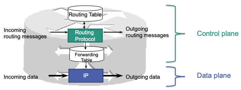
- Control plane
- Exchange of routing messages for calculation of routes …
- Additional tasks, such as load balancing, access control, …
- Data plane: Forwarding of packets at layer 3
Every router has control and data plane functions
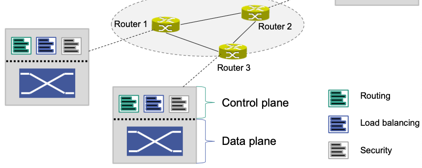
- Control plane: software running on the router
- Data plane
- usually application-specific integrated circuits
- Can also be realized in software (virtual switches)
Control is decentralized.
🔴 Limitations: Limited flexibility for network operators
Manufacturer-specific management interfaces
Difficult (and often impossible) to introduce new functions
Complex, highly qualified operators required
Expensive (at least for core routers)
Current Trend: Software-Defined Networks (SDN)
👍 Advantages
Increase flexibility
Decrease dependencies on hardware and manufactures
Commercial off-the-shelf switches (cheaper)
Characteristics
Separation of control plane and data plane
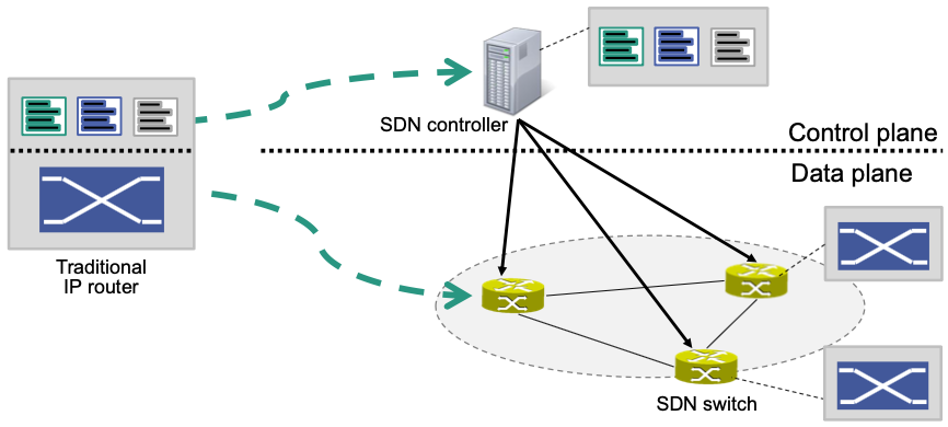
- Control functionality resides on a logically centralized SDN controller
- Controller is executed on commodity hardware Reduces need for specialized routing hardware
- Data plane consists of simple packet processors (SDN switches)
- Control functionality resides on a logically centralized SDN controller
Control plane has global network view
- Knows all switches and their configurations
- Knows network topology
Network is software-programmable
Functionality is provided by network applications (network apps)
Different apps can realize different functionality
SDN controller can execute multiple apps in parallel
Processing is based on flows
Basic Operation
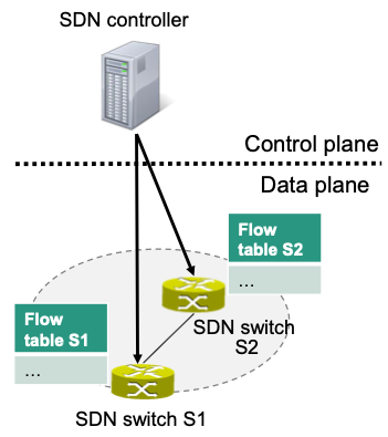
Control functionality is placed on the SDN controller
- E.g., routing including routing table
Forwarding table is placed on SDN switch
- Called flow table in the context of SDN
SDN controller programs entries in flow table according to its control functionality
- Requires a protocol between controller and switch
For every incoming packet in the SDN switch
- Suited entry in flow table needs to be determined
Flows and Flow Table
Flows: sequence of packets traversing a network that share a set of header field values
- Here: Identified through match fields, e.g., IP address, port number
Flow table contains, among others, match fields and actions
Matches select appropriate flow table entry
Actions are applied to all packets that satisfy a match
E.g.

- Flow rule
Decision of controller
Described in form of match fields, actions, switches
Flow Rule and Flow Table Entries
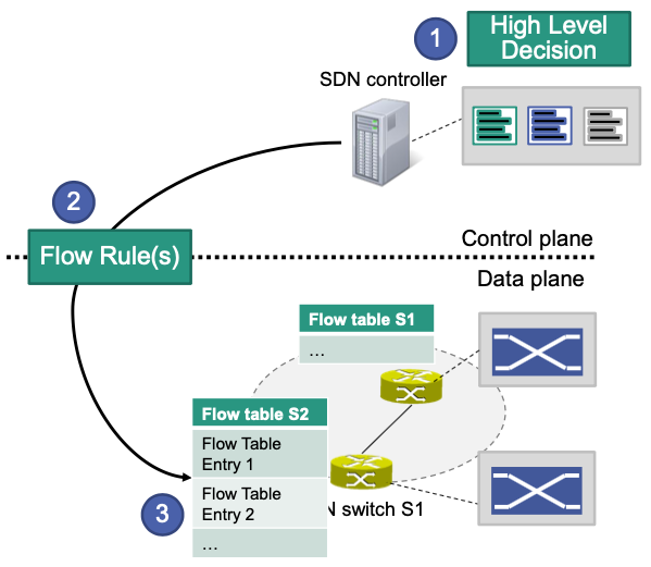
Controller (more precise: app executed by controller) makes a high level decision, for example
a) Traffic for destination X has to be dropped
b) Connection between end system A and B has to go through switch S4
c) …
High level decision is represented in a certain format, i.e., as a set of flow rules in the form of match fields, actions and switches
Flow rules are transmitted (“installed”) to switches with the help of a communication protocol. They are stored as flow table entries in flow tables
Flow Programming
SDN provides two different modes
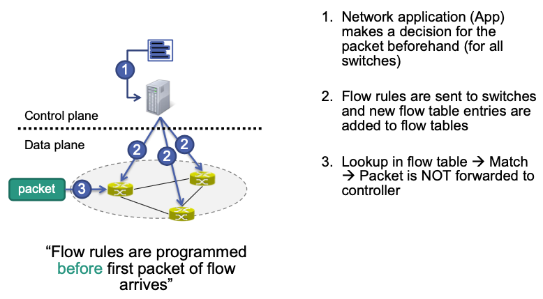
Proactive flow programming
Flow rules are programmed before first packet of flow arrives
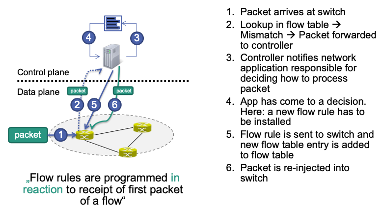
Reactive flow programming
Flow rules are programmed in reaction to receipt of first packet of a flow
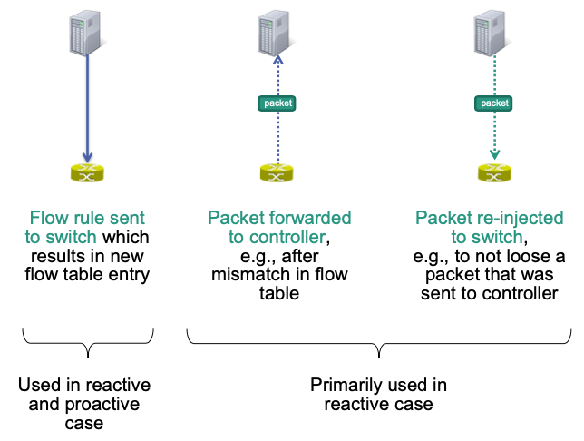
Three Important Interactions
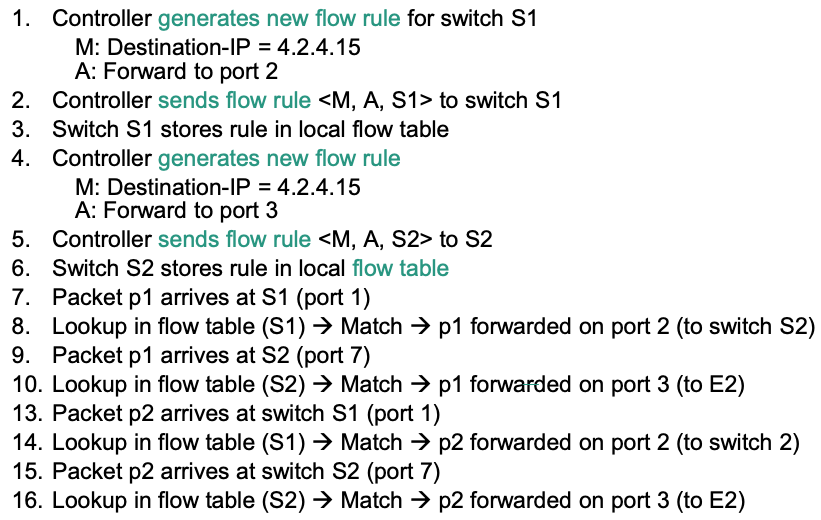
Example: Proactive Flow Programming
Scenario
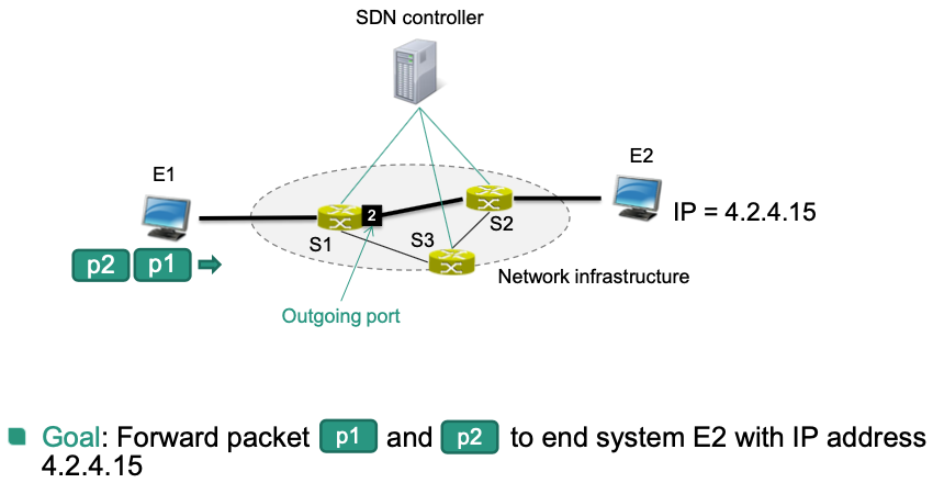
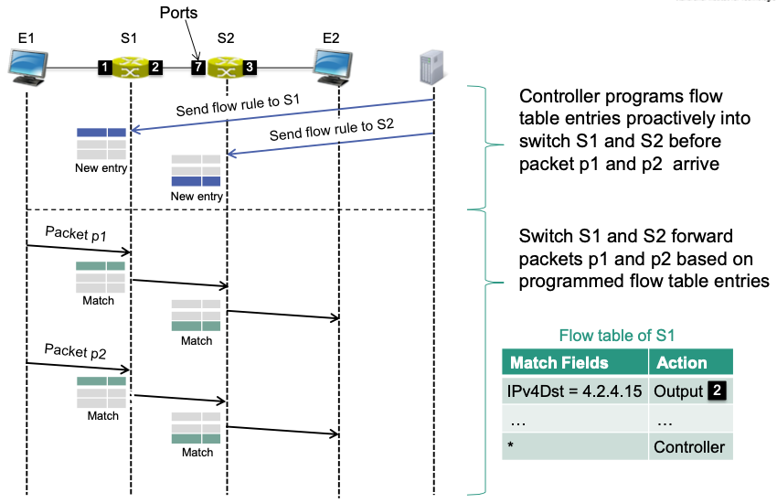
Details
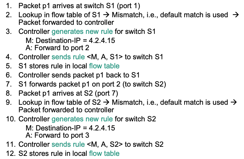
Example: Reactive Flow Programming
Same scenario as above
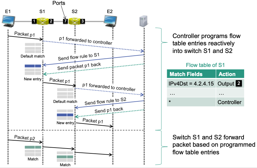
Details

Proactive vs. Reactive Flow Programming
| Flow Programming | Characteristics | Delay? | Loss of controller connectivity |
|---|---|---|---|
| Proactive | coarse grained, pre-defined | No | Does not disrupt traffic |
| Reactive | fine grained, on demand | Yes | New flows cannot be installed |
Proactive
Flow table entries have to be programmed before actual traffic arrives
Usually coarse grained pre-defined decisions
Not always applicable 🤪
No additional delays for new connections
Loss of controller connectivity does not disrupt traffic
Reactive
- Allows fine grained on-demand control
- Increased visibility of flows that are active in the network
- Setup time for each flow High overhead for short lived flows
- New flows cannot be installed if controller connectivity is lost
- Allows fine grained on-demand control
SDN Architecture
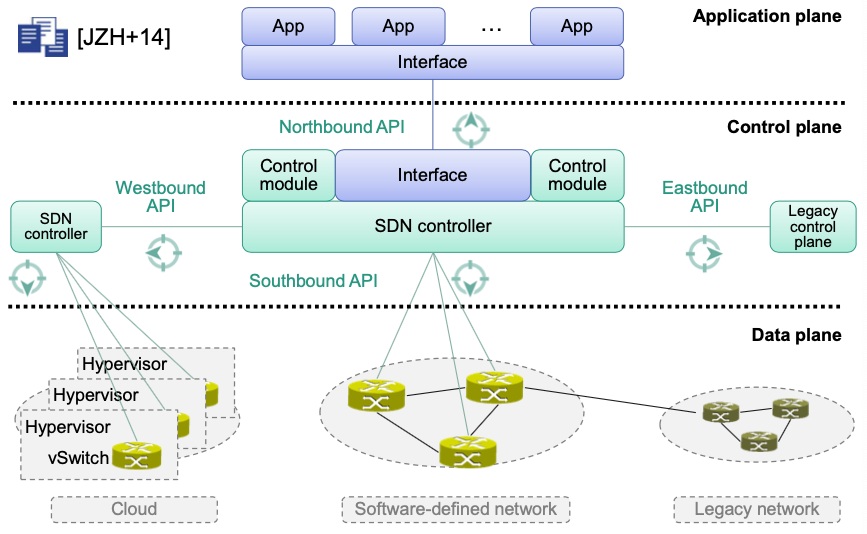
Application Plane
- Network apps perform network control and management tasks
- Interacts via northbound API with control plane
Control Plane
- Control tasks are „outsourced“ from data plane to logically centralized control plane
- E.g., standard tasks such as topology detection, ARP …
- More complex tasks can be delegated to application plane
- E.g., routing decisions, load balancing …
- Control tasks are „outsourced“ from data plane to logically centralized control plane
Data Plane
- Responsible for packet forwarding / processing
- SDN switches are relatively simple devices
- Efficient implementations in hardware (ASIC) or in software (virtual switches)
- Supports basic operations such as match, forward, drop
- Interacts via southbound API with control plane
Interfaces
Northbound API: between controller and network apps
Exposes control plane functions to apps
Abstract from details, apps can operate on consistent network view
Southbound API: between controller and switches
- Exposes data plane functions to controller
- Abstracts from hardware details
Westbound API: between controllers
- Synchronization of network state information
- E.g., coordinated flow setup, exchange of reachability information
Eastbound API: interface to legacy infrastructures
- Usually proprietary
SDN Workflow in Practice
Workflow and Primitives
High level view:
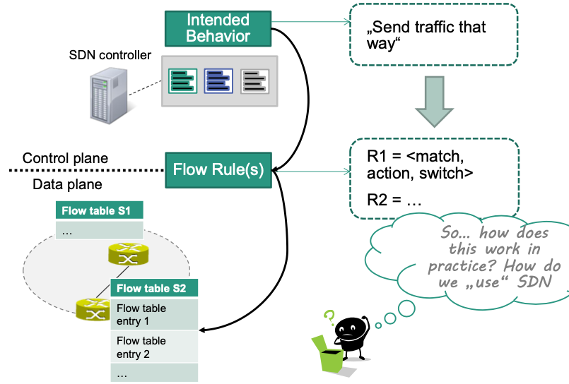
In practice:
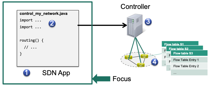
We need a piece of software (app) that realizes the new behavior
control_my_network.javaWe need primitives to assist with creating the app
import OFMatch, OFAction, ...We need a runtime environment that can execute our app
$ ./myController --runApp control_my_network.javaWe need hardware support for SDN in the switches
Flow table(s)
Primitives for SDN Programming
🎯 Goal: From intended behavior to lower level flow rules
This requires SDN programming primitives
Three important areas to cover
(1) Create and install flow rules
Sufficient for proactive use cases.
Example: Traffic with IP destination address 1.2.3.4 has to be forwarded to network B by switch S1
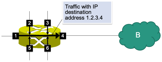
Needed: App that implements the corresponding logic
Represent the decision as flow rules
Program appropriate flow table entries into the switch
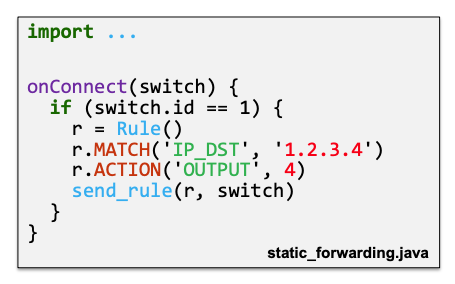
Suppose that we have static_forwarding.java
Creates a new flow rule
Sends the flow rule to S1
Details
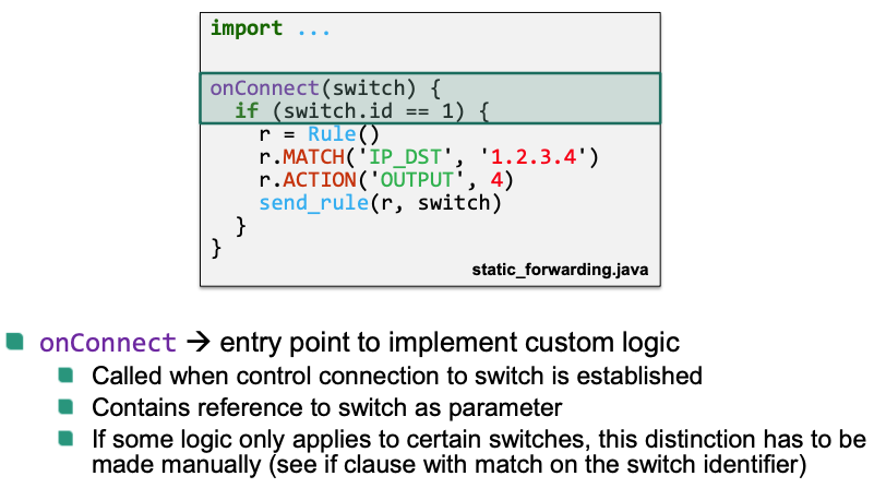
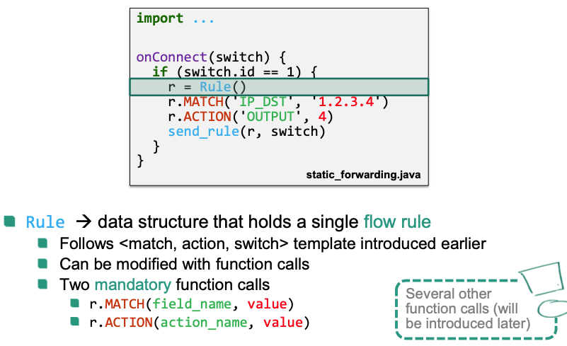
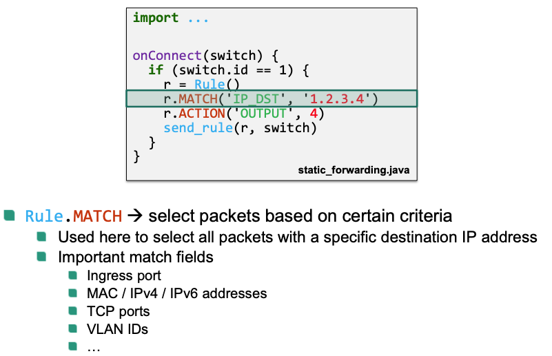
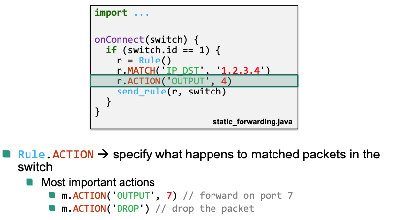
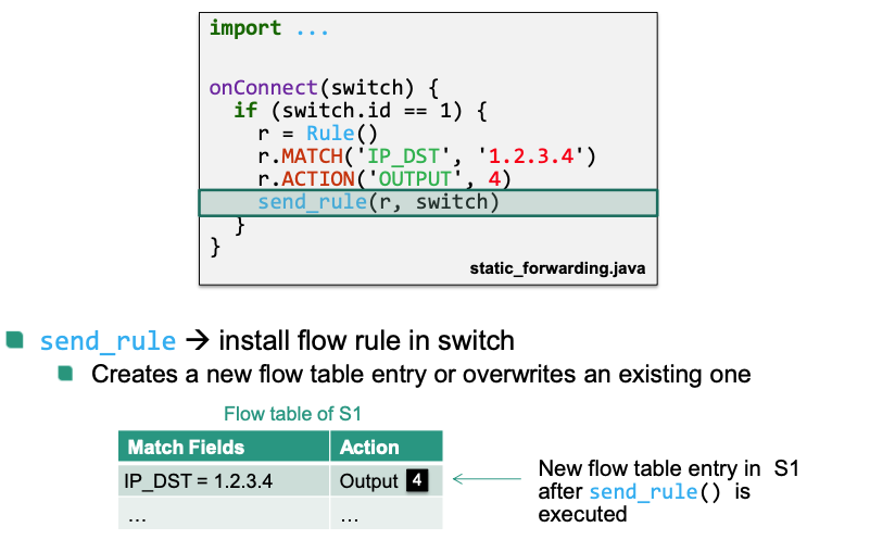
Here we use a simple pseudo programming language
- Language used in practice depends on controller
- Different controllers support different languages: Java, Python, C, C++, …
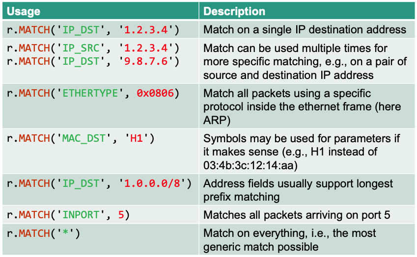
Overview: Matches
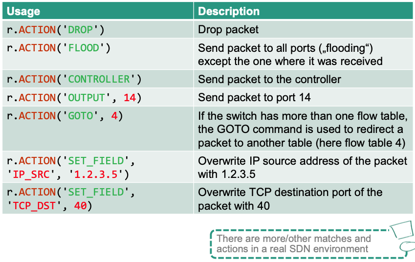
Overview: Actions
Priorities
Priorities come into play if there are overlapping flow rules
- No overlap = all potential packets can only be matched by at most one rule
- Overlap = at least one packet could be matched by more than one rule
Example
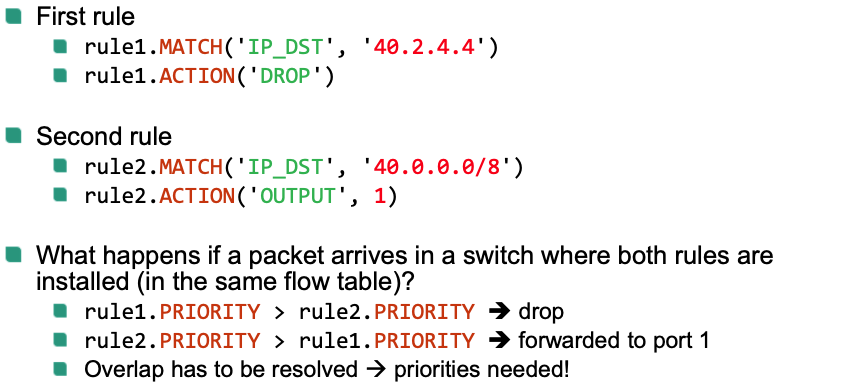
Assume that all rules are created with same default priority (=1)
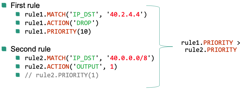
If two rules can overlap, priority has to be changed explicitly
- Higher values = higher priority
Multiple Flow Tables
SDN switches can support more than one flow table

Using multiple tables has several benefits
- Can be used to isolate flow rules from different apps
- Logical separation between different tasks (one table for monitoring, one table for security, …)
- In some situation: less overall flow table entries
Similar to single table case
r.TABLE(x): specify the table for this ruler.ACTION('GOTO', y): specify processing continues in another table
Avoid cycles: Can NOT go to lower flow table number
GOTOfrom table x to table y y > x
Example

(2) React to data plane events
onPacketIn(packet, switch, inport)- Called if the controller receives a packet that was forwarded via
r.ACTION('CONTROLLER') - Parameters
packet: contains packet that was forwarded and grants access to its header fieldspacket.IP_SRCpacket.IP_DST
packet.MAC_SRCpacket.MAC_DSTpacket.TTL- …
switch: the switch the packet was received at (e.g., S1)inport: the interface the packet was received at (e.g., port 1)
- Called if the controller receives a packet that was forwarded via
Example
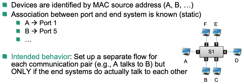
Sketch
Create a low priority flow rule that sends „all unknown packets“ to the controller
r.MATCH('*') // match on everything r.ACTION('CONTROLLER') // send packet to controller r.PRIORITY(0) // use lowest priority for this flow ruleUse
onPacketIn()to create and install flow rules on demand
Details
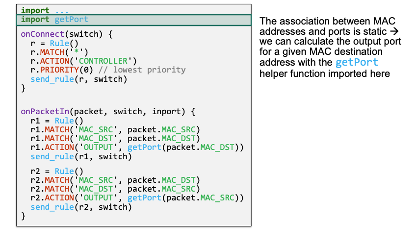
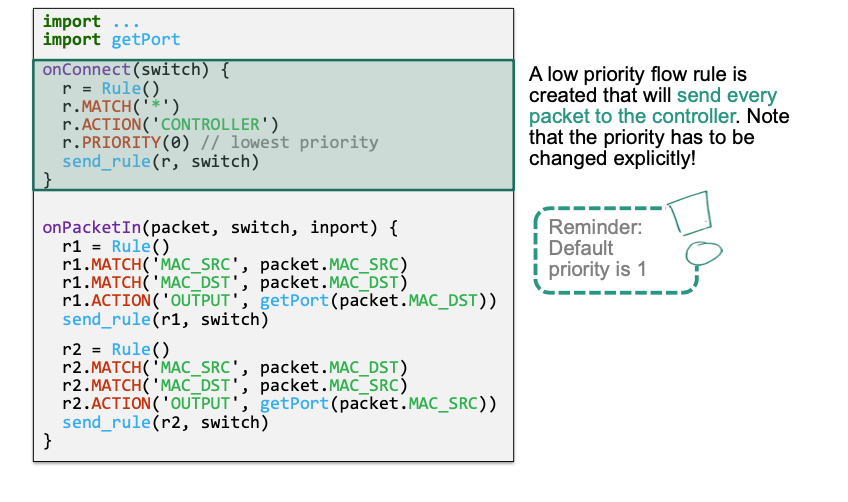
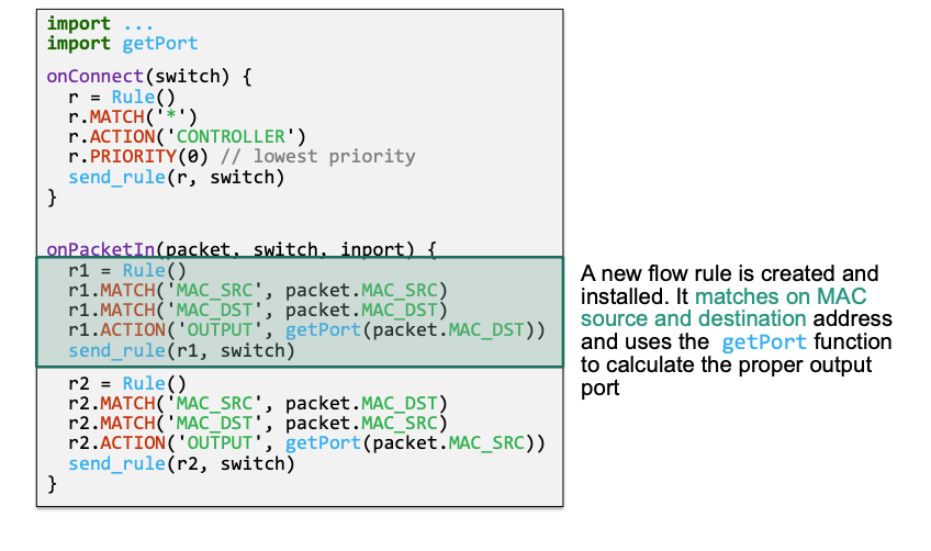
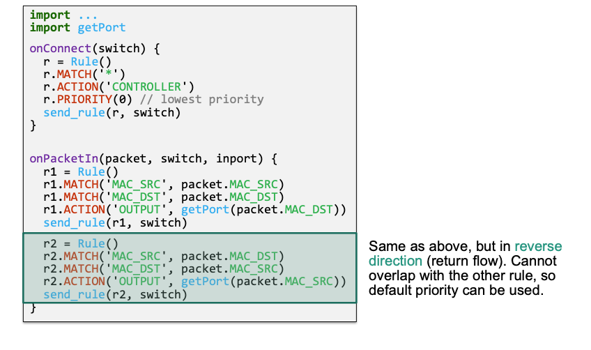
(3) Inject individual packets
Handle individual packets from within the app
- Forward a packet that was sent to the controller
- Perform topology detection
- Active monitoring („probe packets“)
- Answer ARP requests
send_packet(packet, switch, rule)
Injects a single packet into a switch
Parameters
packet: contains the packet that should be injectedswitch: the switch where the packet is injectedrule: a flow rule that is applied to this packet instead of default flow tableprocessing (optional)
- Only
rule.ACTION()is allowed here - No matches, no priorities
- Only
Different from installing flow rules
- Used for a single packet only
- The flow table is not changed
- Even if the
ruleparameter is present, this does NOT create a new flow table entry
Inject and process injected packet with a custom rule
- Directly attaches the actions to the injected packet
- Rule is only used for a single packet
- Flow table remains unchanged
- Advantages
- Efficient
- Consistent
Example
newPacket = createNewPacket()
customRule = Rule()
customRule.ACTION('OUTPUT', 1)
send_packet(newPacket, switch, customRule)
Summary on Primitives
Entry point primitves: Callbacks to implement custom logic
onConnect(switch)Called if a new control connection to switch is established
onPacketIn(packet, switch, port)Called if a packet was forwarded to the controller
Flow rule creation primitives: Used to define flow rules
Rule.MATCH()Select packets based on certain header fields
Rule.ACTION()Specify what happens to a packet in the switch
Rule.PRIORITY()Specify the priority of the created flow rule
Rule.TABLE()Specify the flow table the rule should be applied to
Switch interaction primitives: Used to handle flow rule installation and packet injection
send_rule(rule, switch)Installs a flow rule and creates the associated flow table entry in the switchsend_packet(packet, switch)Injects a single packet into a switch, process with existing flow table entriessend_packet(packet, switch, rule)Injects a single packet into a switch, process with custom rule
Learning Switch Example
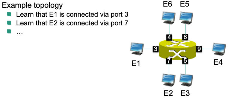
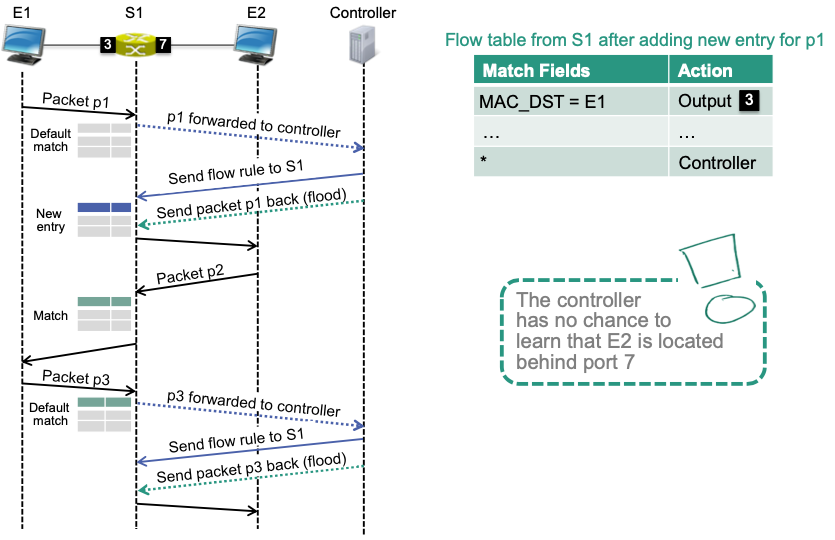
Goal: learn port-address association of end systems
Switch receives packet and does not know destination address
Floods packets on all active ports
Learns “location” of the end system with this destination
address
- Remembers that end system is accessible via this port - Entry in table `<MAC address, port, lifetime>`
Switch receives packet and knows destination address
- Forwards packet via corresponding port
We can do the same with SDN: Learning switch app
- Observe packets by controller
- Derive locations of end systems
- Program forwarding rules to allow connectivity between end systems based on MAC addresses and port numbers
Naïve Approach
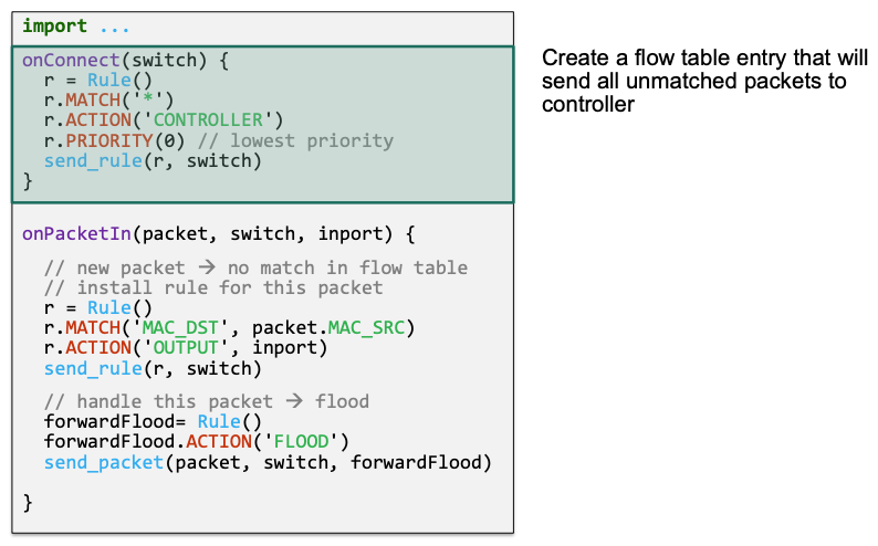
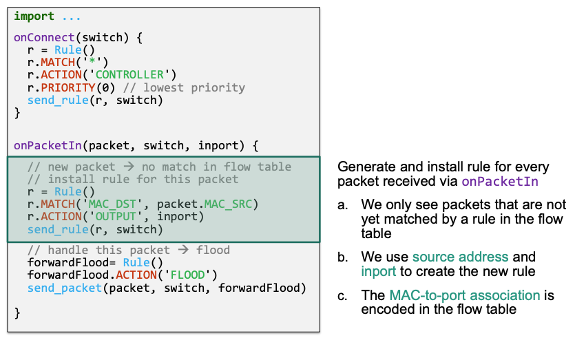
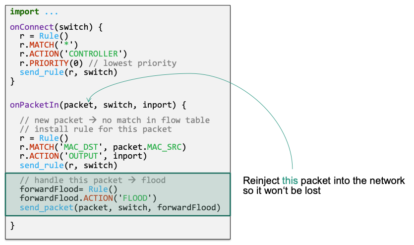
Send all packets to controller
Controller looks at
INPORTand source MAC addressController creates rules based on these two pieces of information
Packets with unknown destination addresses are flooded to all ports
Implementation
🔴 Problem
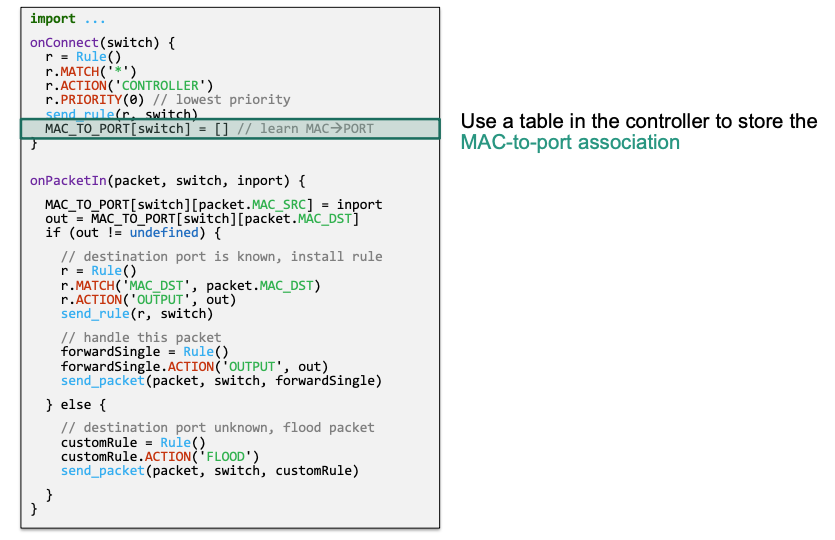
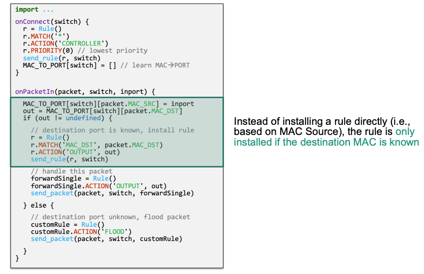
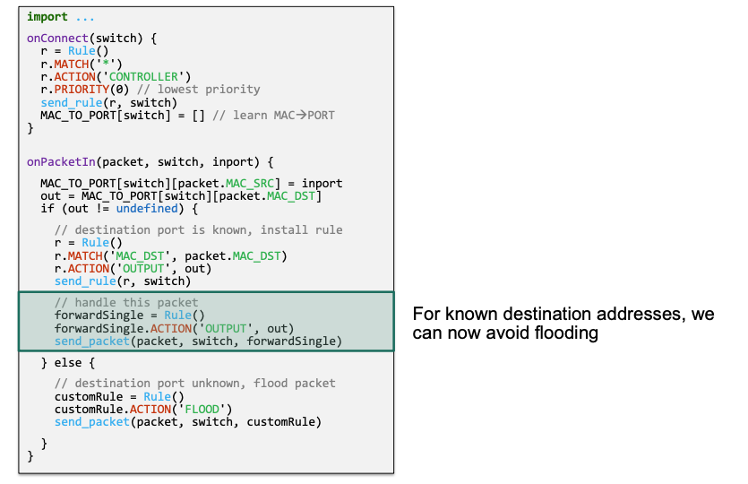
Version 2
- Delay rule installation until the destination address was learned (not the source address)
- Avoids installing rules „too early“
Implementation
Consider the example above:
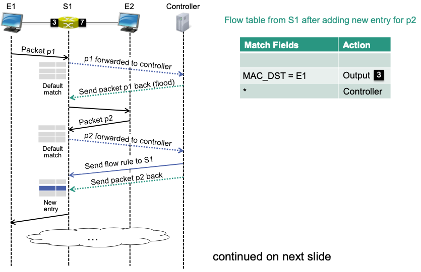
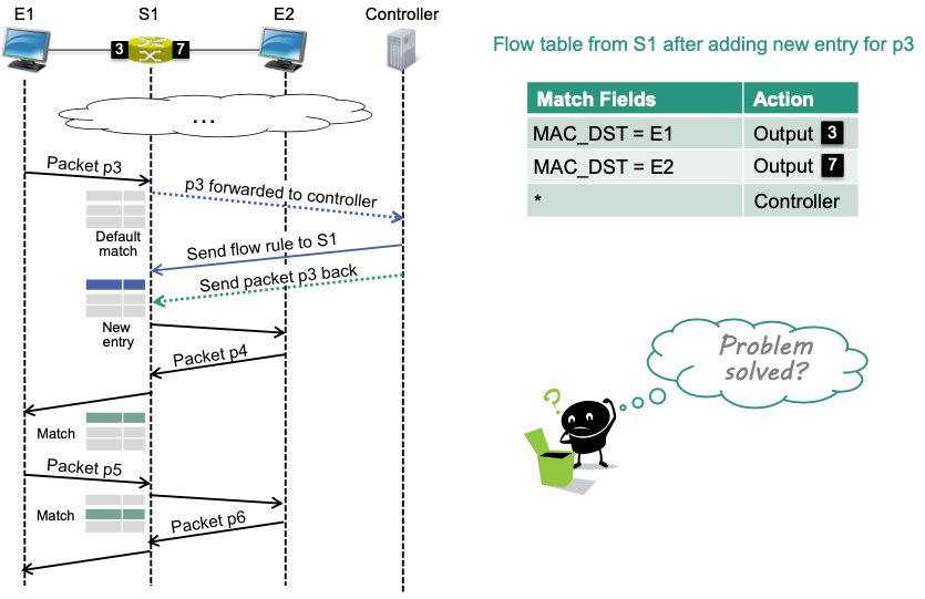
🔴 Problem
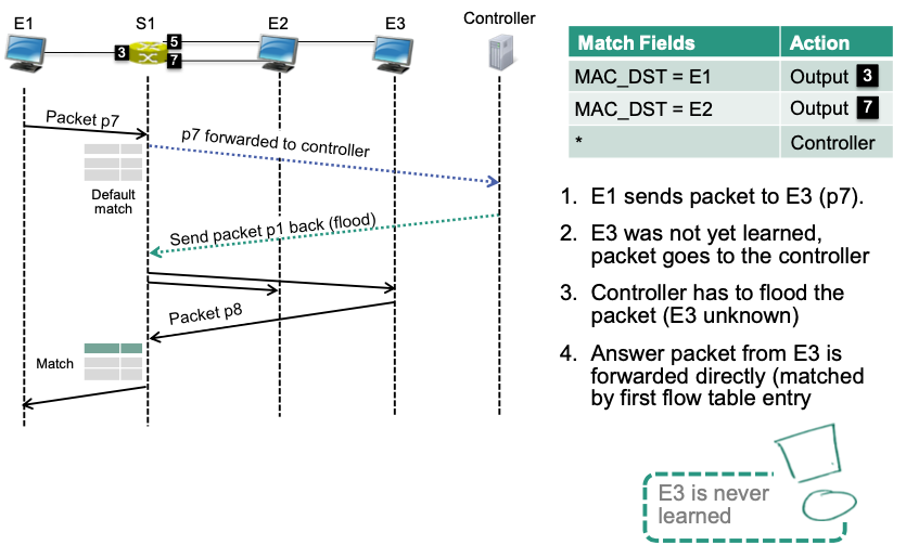
Version 3
- Only matching on destination address is not specific enough
- Use more specific matches
- Makes sure that all end systems can be learned by controller
Implementation
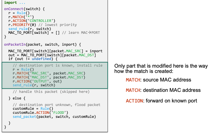
Consider the example in Version 2:
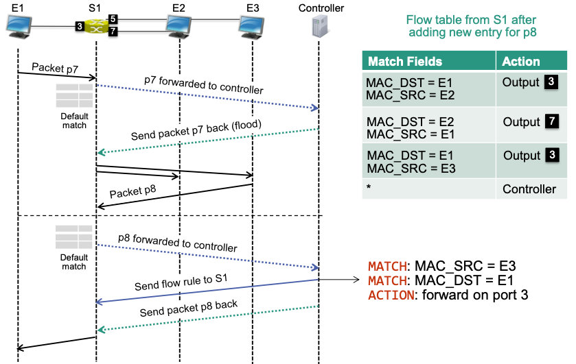
🔴 Problem: flow table resources
- Needs N*N flow entries for N end systems
- May exceed table capacity! 🤪
Version 4
Separate flow tables for learning and forwarding
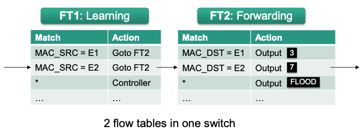
- Flow table FT1 matches on source address and forwards to controller, if address was not yet learned
- Flow table FT2 matches on destination address and forwards packet to destination (if learned) or floods packet (if not learned)
Only 2*N rules for N end systems
🔴 Problem: Hardware often does not support multiple flow tables due to cost, energy or space constraints
OpenFlow
Rough Overview
A standard for an SDN southbound interface
- Defines the interaction between controller and switches
- Defines a logical architecture for SDN switches (flow table, …)
- Defined by the Open Networking Foundation (ONF)
Supports
- All basic structures and primitives discussed in previous section
Matches
Actions
Priorities
Multiple flow tables
Protocol mechanisms for
Creating flow rules
Reacting to data plane events
Injecting individual packets
- More sophisticated features
- Group table
- Rate limiting
- All basic structures and primitives discussed in previous section
Structure
Provides a uniform view on SDN-capable switches
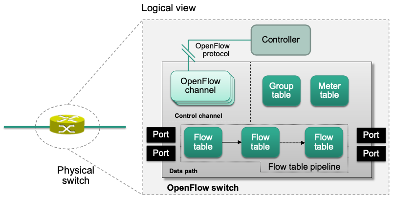
Ports
Represent logical forwarding targets
Can be selected by the output action
Physical ports = hardware interfaces
Reserved ports (special meaning)
ALL- Represents all ports eligible to forward a specific packet (= flooding);
- Ingress port is automatically excluded from forwarding
IN_PORTAlways references ingress port of a packet (= send packet back the way it came)
CONTROLLERForwarding a packet on this port sends it to the controller
NORMALYields control of the forwarding process to the vendor-specific switch implementation
Logical ports
Provide abstract forwarding targets (vendor-specific)
Link aggregation: Multiple interfaces are combined to a single logical port
Transparent tunneling: Traffic is forwarded via intermediate switches
Flow table

Counters
The number of processed packets (counter)
Timeouts
Maximum lifetime of a flow
Enables automatic removal of flows
Cookie
- Marker value set by an SDN controller
- Not used during packet processing
- Simplifies flow management
Flags
Indicate how a flow is managed
E.g., notify controller when a flow is automatically removed
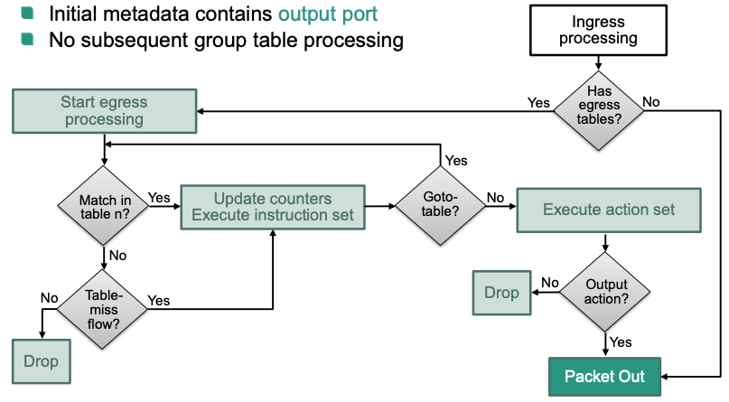
Pipeline Processing
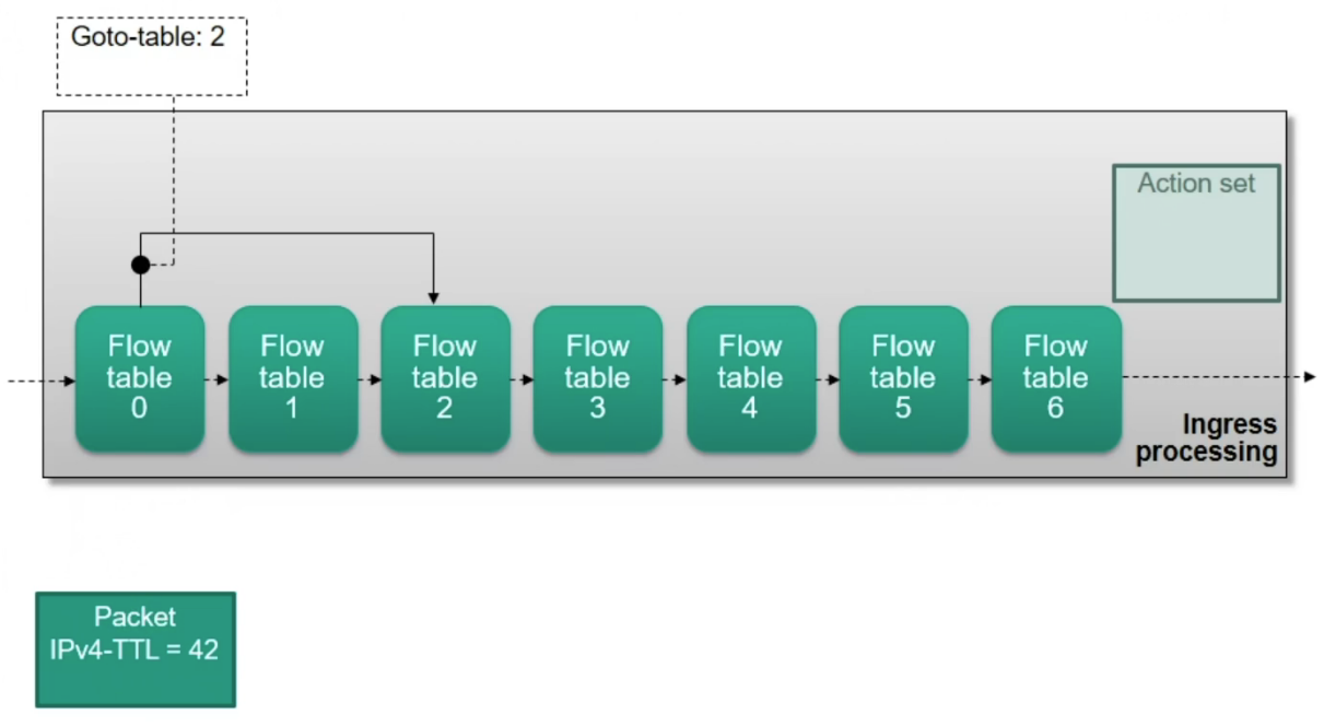
Multiple flow tables can be chained in a flow table pipeline
Flow tables are numbered in the order they can be traversed by packets
Processing starts at flow table 0
Only “forward” traversal is possible no recursion
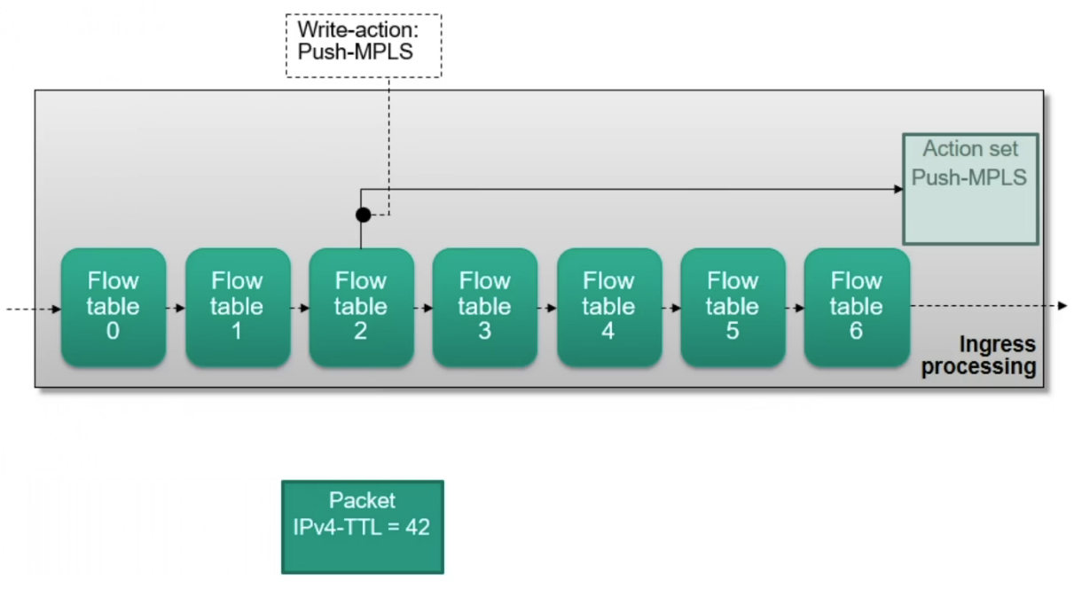
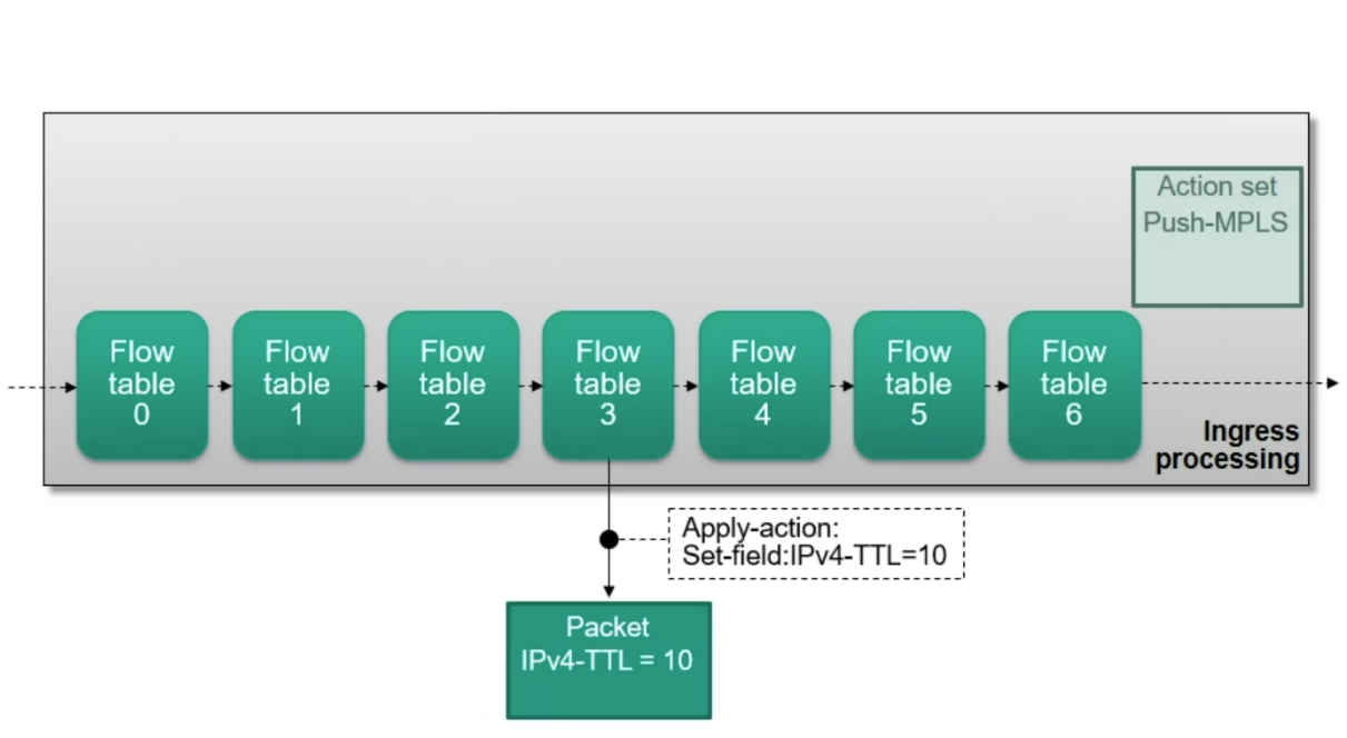
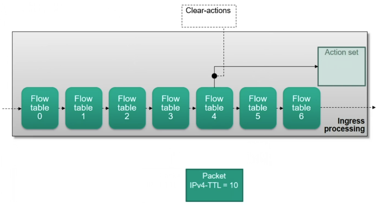
Actions are accumulated in an action set during pipeline processing
Divided into ingress and egress processing
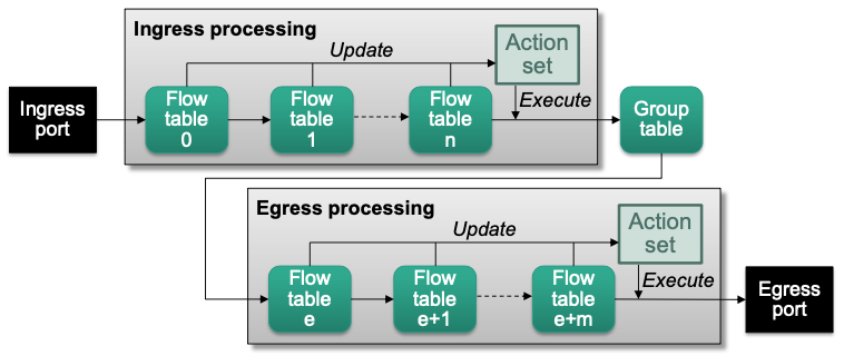
Example
Building an action set
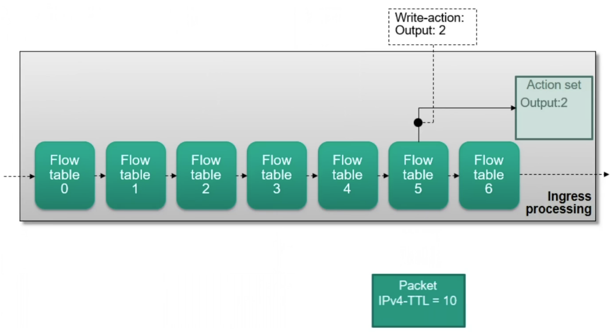
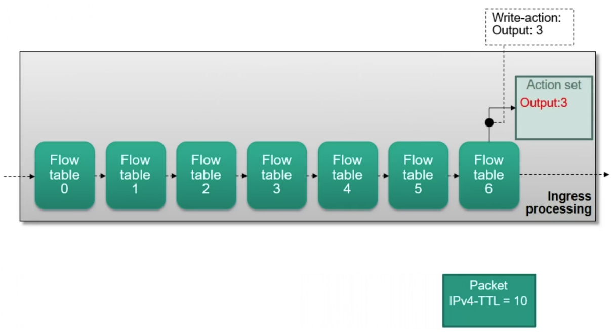
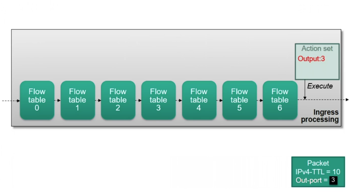
Ingress Processing
- Starts at flow table 0
- Initial action set is empty
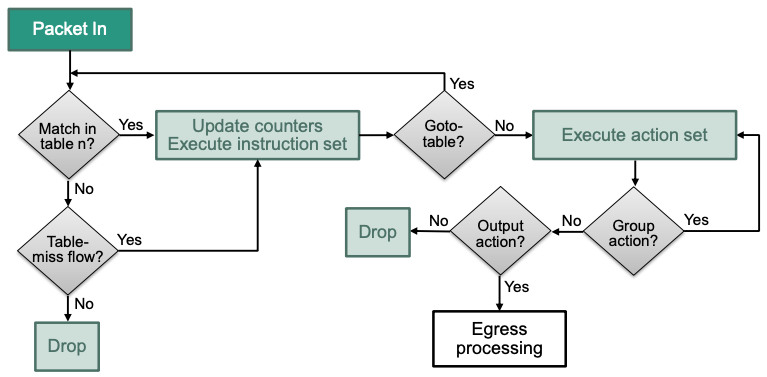
Egress Processing
Optionally follows ingress or group table processing
- Egress flow tables must have higher table numbers than ingress tables No return to ingress processing
Group Tables
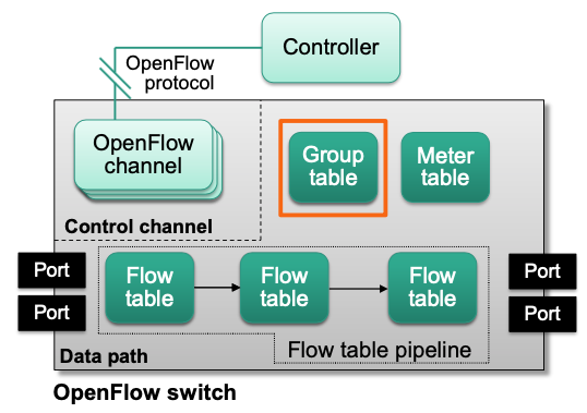
Grout entry:

Group tables represent additional forwarding methods (E.g., link selection, fast failover, …)
Group entries can be invoked from other tables via group actions
They are referenced by their unique group identifier
Flow table entries can perform group actions during ingress processing
Effect of group processing depends on the group type and its action buckets
Action buckets
- Each group references zero or more action buckets
- Not every action bucket of a group has to be executed
- A group with no action buckets drops a packet
- An action bucket contains a set of actions to execute (just like an action set)
- Each group references zero or more action buckets
Group types
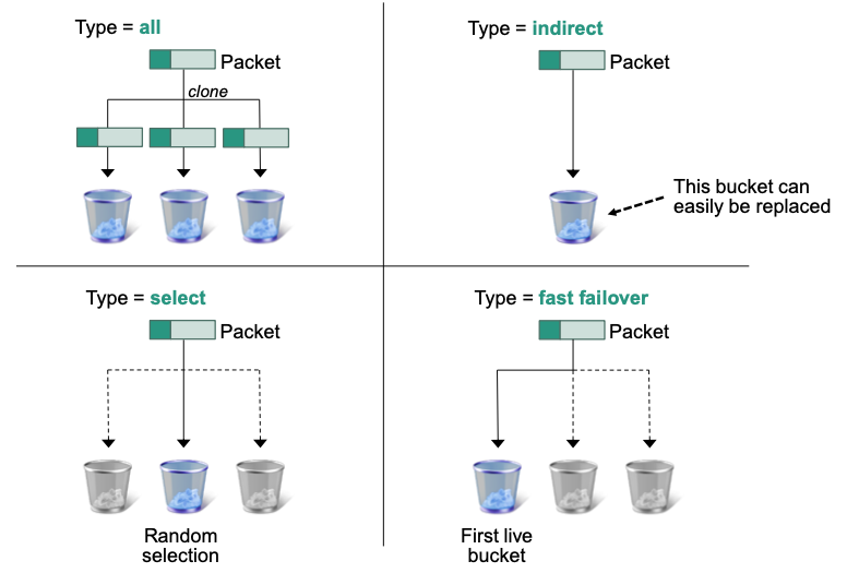
- All: executes all buckets in a group (E.g., for broadcast)
- Indirect: executes the single bucket in a group
Indirect groups must reference exactly one action bucket
Useful to avoid changing multiple flow table entries with common actions
- Select: selects one of many buckets of a group (E.g., select by round-robin or hashing of packet data)
- Fast failover: executes first live bucket in a group
- Each bucket is associated with a port that determines its liveliness
Example
Indirect Group Tables
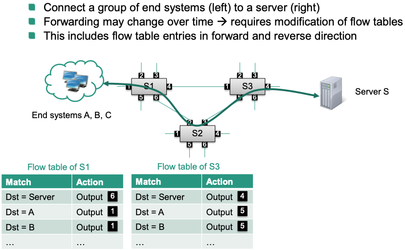
🎯 Goal: Reroute flows to avoid forwarding via switch S2
Output ports specified in flow tables are subject to change
SDN controller must send multiple modify-state messages to SDN switches
One message for each flow that needs to be updated 🤪
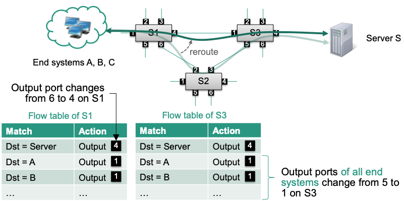
Optimization
- Use an indirect group to avoid sending multiple modify-state messages
- Redirect flows with identical forwarding behavior to that group
- Modify the groups actions when forwarding behavior changes
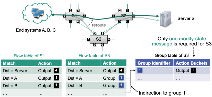
Advantage: Instead of modifying a great number of entries in flow table, we just need to modify one entry in group table!
Additional material on OpenFlow
Flow Table in OpenFlow
Flow tables contain match/action-associations
- Matches select the appropriate flow table entries
- Actions are applied to all packets that satisfy a match
Table-miss flows capture all unmatched packets
- Enables reactive flow programming
- Corresponding flow table entry has lowest priority
- Synonym: default flow
Example

Matches in OpenFlow
Matches have priorities
- Only the entry with the highest priority is selected
- Disambiguation of similar match fields

Wildcard matching can be performed using bitmasks
Empty match fields match all flows
Actions in OpenFlow
Basic functionality is simple: „determine what happens to a packet“
In reality, OpenFlow makes a distinction between actions, action sets and more general instructions (linked to how the OpenFlow pipeline works)
Action
- A concrete command to manipulate packets like „output on port“ or „push MPLS“
- OpenFlow supports
- Output: forwards a packet
- Set-field: modifies a header field of a packet
- Push-tag: pushes a new tag onto a packet
- Pop-tag: removes a tag from a packet
- Drop a packet: Implicitly defined when no output action is specified
Action set
Every packet has its own ActionSet while processed
Changes to the packet can be stored in the set / deleted from the set
Actual changes are applied when processing ends
Set is carried between flow tables (in one switch)
An action set contains at most one action of a specific type
- Previous instances are overwritten
- An action set may contain multiple set-field actions
Execution proceeds in a well-defined order
Modifications to the action set
- write-actions: writing new actions to a set
- clear-actions: Removing all actions from the set
(Check out the example in Flow Table)
Instructions
- Control how packets are processed in the switch
- Each flow table entry is associated with a set of instructions
Change the packet immediately (
apply-action)Change the action set
Continue processing in another table (
goto-table command)
OpenFlow Channel
Connects each switch to a controller
Provides the southbound API functionality of an OpenFlow switch
Management and configuration of switches by controllers
Signaling of events from switches to controllers
Monitoring of liveliness, error states, statistics, …
Experimentation
Multiple channels to different controllers can be established
Three message types
Controller-to-Switch messages
Inject controller-generated packets (packet-out message)
Modify port properties or switch table entries (modify-state message)
Collect runtime information (read-state message)
Asynchronous messages
- Packet-in message transfers control of packet to the controller
- State changes signaled by switches
Symmetric messages
Handle connection setup and ensure correct operation
- Hello: exchanged on connection startup (e.g., indicate supported versions)
- Echo: verify lifelines of controller-switch connections
- Error: indicate error states of the controller or switch
Experimenter messages can offer additional functionality
Meter Tables
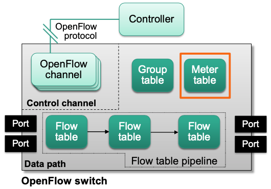
- Meter table entry

Meters measure and control the rate of packets and bytes
They are managed in the meter table
Each meter has a unique meter identifier
Meters are invoked from flow table entries through the meter action
When invoked, each meter keeps track of the measured rate of packets
One of several meter bands is triggered when the measured rate exceeds that bands target rate
Meter bands

- Packet processing by a meter band depends on its band type
- DSCP remark: implements differentiated services
- Drop: implements simple rate-limiting
- Rate and burst determine when a band is executed
- Band types may have additional type-specific arguments
- Packet processing by a meter band depends on its band type
The Power of Abstraction
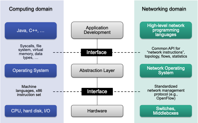
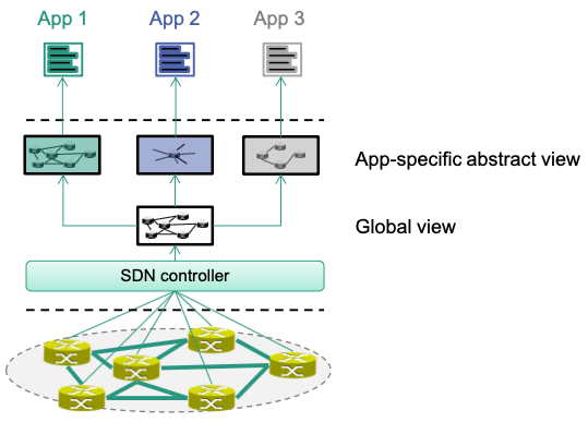
Different Abstractions for Different Apps
Controller can provide different abstractions to network apps
Apps should not deal with low level / unnecessary details
Apps only have an abstract view of the network
Global view of controller can be different from abstract view of an app
Examples
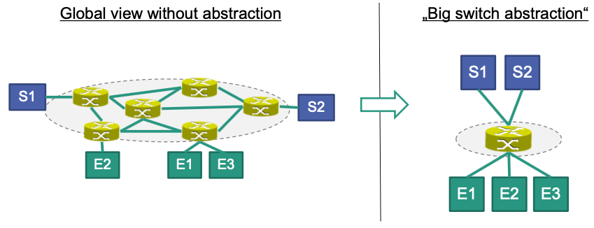
“Big Switch Abstraction”
Consider a security application that manages access control lists
Controls the access of end systems E1, … En to services S1, … Sm
Details such as the exact position of an end system / service are not required for the application Can be hidden in the abstraction
Network Slicing
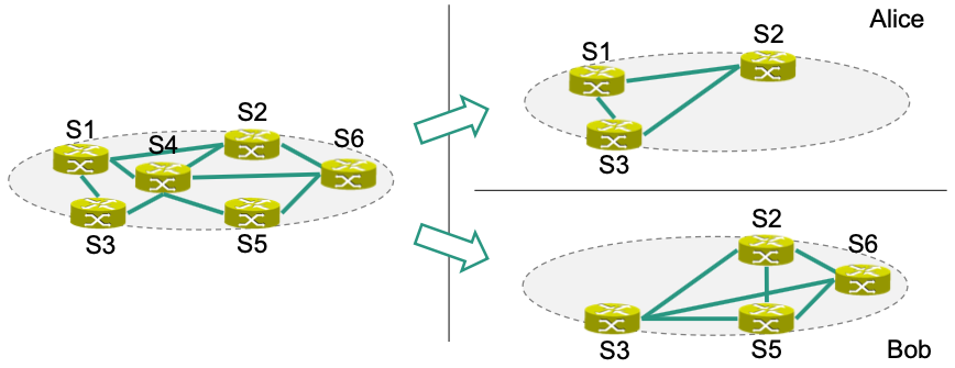
Consider a network that has to be virtualized between multiple customers, e.g., Alice and Bob
Alice is only allowed to utilize S1, S2, and S3
Bob is only allowed to utilize S2, S3, S5, and S6
Both customers get an individual (full-meshed) view of the network
- This is often called a network slice
🔴 SDN Challenges
Controller connectivity
SDN requires connectivity between controller and switches
Two different connectivity modes
Out-of-band
Dedicated (physical) control channel for messages between controller and switch
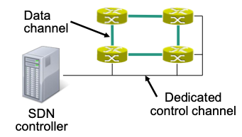
Cost intensive
In-band
Control messages use same channel as “normal” traffic (data)
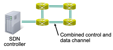
Multiple applications can configure switch
Scalability
Logically centralized approach requires powerful controllers Size / load of bigger networks can easily overload control plane 🤪
Important parameters with scalability implications
Number of remotely controlled switches
Number of end systems / flows in the network
Number of messages processed by controller
Communication delay between switches and controller
Possible solution: Distributed controllers
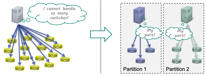
Consistency
Network view must remain consistent for applications
- Synchronize network state information
- Done via the westbound interface
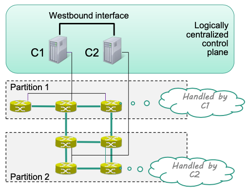
Controller directly applies internal operations (inside partition) and notifies remote controllers of relevant changes of the network
- E.g C1 applies internal operations in Partition 1 and then notifies C2 of the change.
Apps can perform data plane operations on remote switches
- Apps operate on a consistent network view
- Operations are delegated to responsible SDN controller
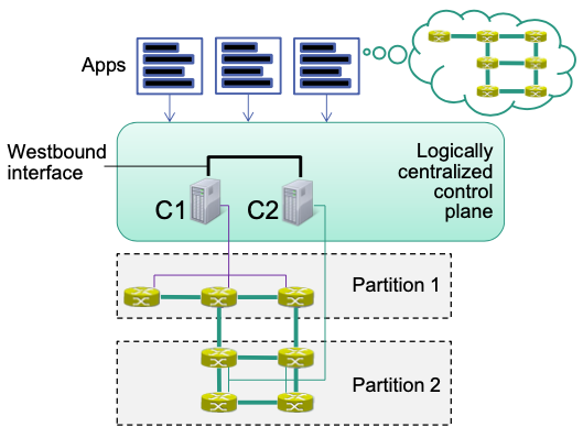
Note: Control plane with multiple controllers is a distributed system
Desirable properties
Consistency
System responds identically to a request no matter which node receives the request (or does not respond at all)
Availability
System always responds to a request (although response may not be consistent or correct)
Partition tolerance
System continues to function even when specific messages are lost or parts of the network fail
CAP theorem
It is impossible to provide (atomic) consistency, availability and partition tolerance in a distributed system all at once
Only two of these can be satisfied at the same time
Data plane limitations
- Flow Table Capacity
- Flow Setup Latency
SDN Use Cases
- Google B4
- Defense4All
- VMWare NSX
Tools
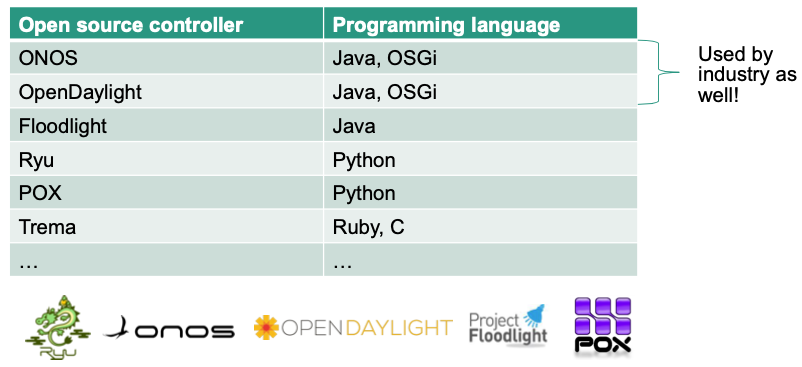
Controller Platforms
Virtual Switches
- Core component in modern data centers
- Used as “virtual” Top-of-Rack switches
Flow Programming Example
This example is taken from HW09.
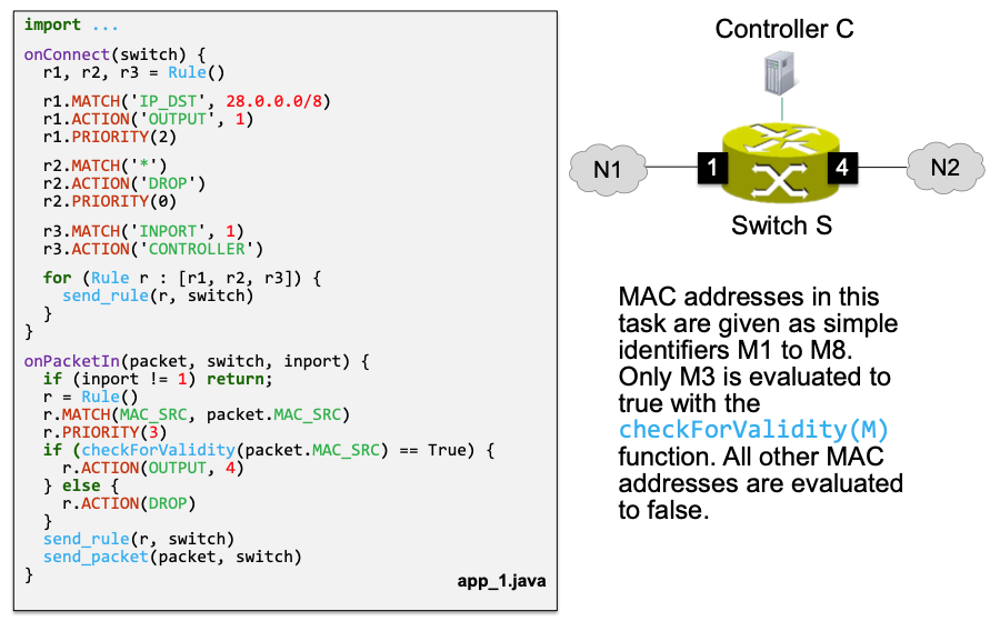
Describe the functionality that is implemented by app_1.java
The application has proactive and reactive parts
Proactive:
onConnect()r1: Forward all packets whose IP destination address belongs to28.0.0.0/8to port 1 (i.e. network N1)r2: Default rule, drops everythingr3: Send packets from N1 to controller
Reactive
onPacketIn()- If a packet is sent to controller by
r3, check whether the MAC address is valid. If valid, then forward to port 4 (i.e, network N2). Otherwise drop.
- If a packet is sent to controller by
What port is connected to the Internet in the given example?
A reasonable assumption here is that N1 is the internal network (because the application can check source validity with MAC addresses) and N2 is the Internet (i.e., the answer is port 4)
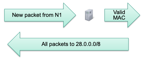
Why r2.PRIORITY(0) is required?
r2.PRIORITY(0) is required, because r2 is the default rule in this case
- Default rules usually have
*match - 0 is the lowest priority (lower than the default priority = 1)
why r1.PRIORITY(2) is required?
r1.PRIORITY(2) is required to enforce that the there are no rule overlaps
- With default priority on
r1,r1andr3would overlap if a packet from N1 is sent with destination address in 28.0.0.0/8
Draw a sequence diagram illustrating the processing of the six consecutive packets P1 - P6 shown below. The diagram should contain the two networks (N1, N2), the switch (S) and the controller (C). Mark the arrows with send_rule, packet_in and send_packet

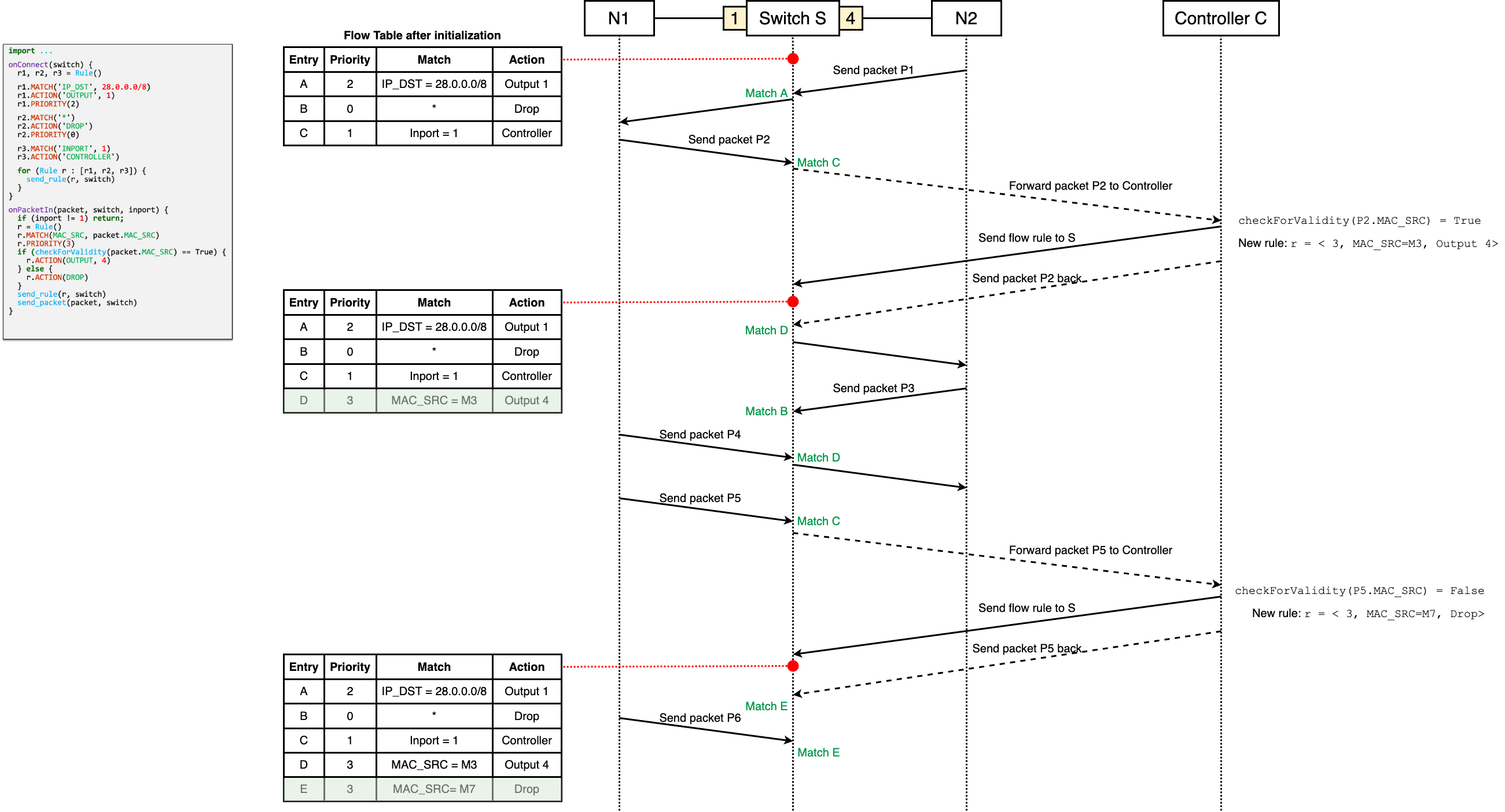
Solution