Data Center
Summary of fat tree
Introduction
Data Center
- Typiically has
- Large number of compute servers with virtual machine support
- Extensive storage facilities
- Typically uses
- Off-the-shelf commodity hardware devices
- Huge amount of servers
- Switches with small buffers
- Commodity protocols: TCP/IP, Ethernet
- Off-the-shelf commodity hardware devices
- Should be
- Extensible without massive reorganization
- Reliable
- Requires adequate redundancy
- Highly performant
Data Center Network
- Interconnects data center servers and storage components with each other
- Connects data center to the Internet
- Two types of traffic
- Between external clients and internal servers
- Between internal servers
- Border routers: Connect internal network of the data center to the public Internet
- Commodity protocols
- TCP/IP
- Ethernet
Simplified Sketch
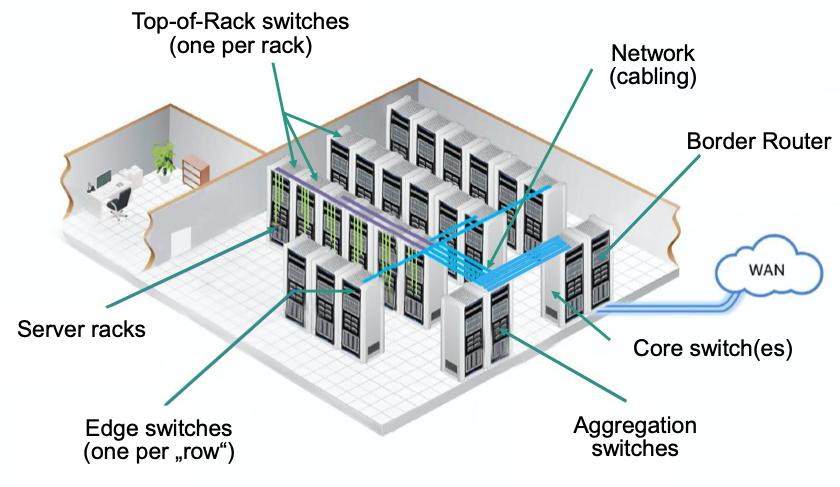
Top-of-Rack (ToR) Ethernet switches
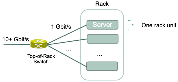
- connect servers within a rack
- Switches typically have small buffers
- Can be placed directly at the „top“ of the rack
- Typical data center rack has 42-48 rack units per rack
Routing/Forwarding within Data Center
Requirements
Efficient way to communicate between any two servers
Utilize network efficiently
Avoid forwarding loops
Detect failures quickly
Provide flexible and efficient migration of virtual machines between servers
Fat-Tree Topologies
🎯 Goal: Connect large number of servers by using switches that only have a limited number of ports
Characteristics
- For any switch, number of links going down to its children is equal to the number of links going up to its parents
- The links get „fatter“ towards the top of the tree
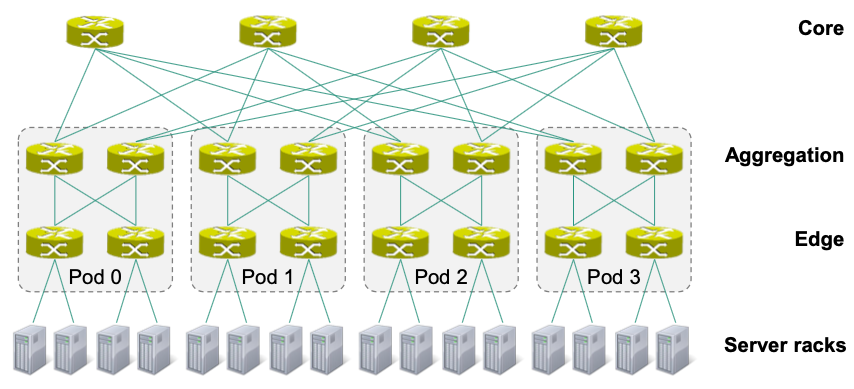
Structure
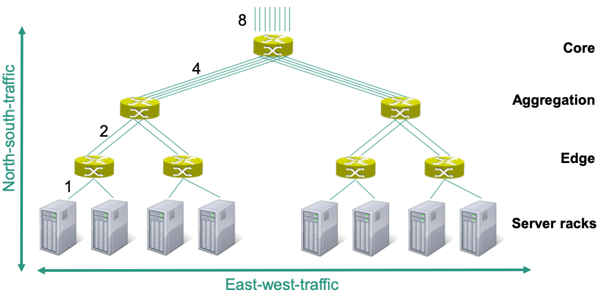
East-west traffic
Between internal servers and server racks
Result of internal applications, e.g.,
- MapReduce,
- Storage data movement between servers
North-south traffic
- Result of external request from the public Internet
- Between external clients and internal servers
🔴 Problems: Switches need different numbers of ports
- Switches with high number of ports are expensive 💸
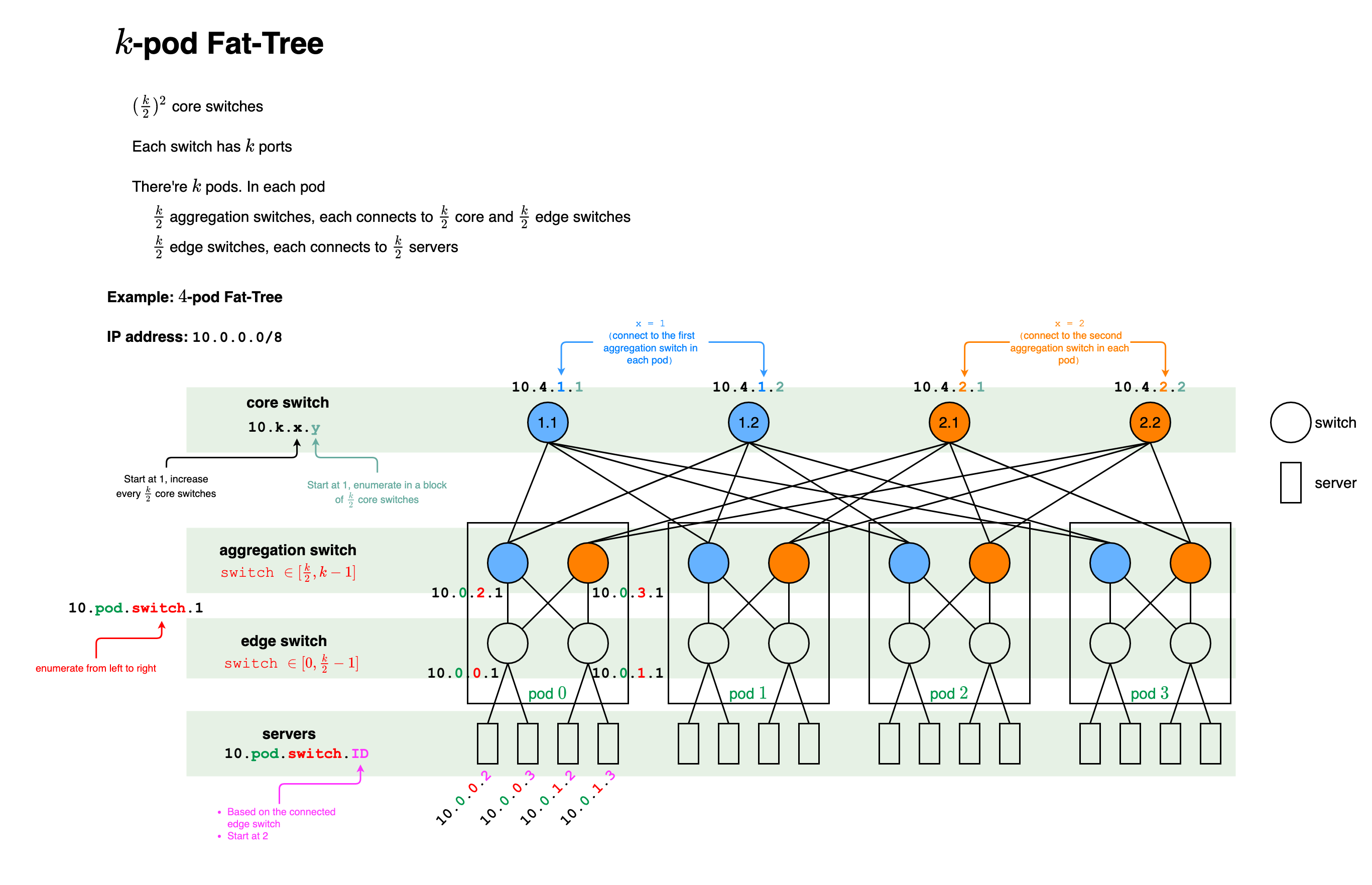
K-Pod Fat-Tree
Each switch has $k$ ports
Edge and aggregation switch arranged in $𝑘$ pods
$\frac{k}{2}$ edge switches and $\frac{k}{2}$ aggregation switches per pod
$\Rightarrow$ Overall: $\frac{k^2}{2}$ edge and $\frac{k^2}{2}$ aggregation switches
$\Rightarrow$ $k^2$ switches in all pods
$(\frac{k}{2})^2$ core switches, each connects to $k$ pods
$\Rightarrow$ Overall $k^2 + (\frac{k}{2})^2 = \frac{5}{4}k^2$ switches
Each edge switch connected to $\frac{k}{2}$ servers
$\Rightarrow$ Overall $\frac{k^2}{2} \cdot \frac{k}{2} = \frac{k^3}{4}$ can be connected
Each aggregation switch connected to $\frac{k}{2}$ edge and $\frac{k}{2}$ core switches
$\Rightarrow$ Overall $2 \cdot (k \cdot \frac{k}{2}) \cdot \frac{k}{2} = \frac{k^3}{2}$ links (links to servers not included)
Summary: $k$-pod fat-tree
Component number pod $k$ edge switch $\frac{k^2}{2}$ aggregation switch $\frac{k^2}{2}$ core switch $(\frac{k}{2})^2$ server $\frac{k^3}{4}$ links between switches $\frac{k^3}{2}$
Every link is in fact a physical cable $\rightarrow$ high cabling complexity 🤪
Example: $k(=4)$-Pod Fat-Tree
👍 Advantages
All switches are identical
Cheap commodity switches can be used
Multiple equal cost paths between any hosts
🔴 Disadvantages: High cabling complexity
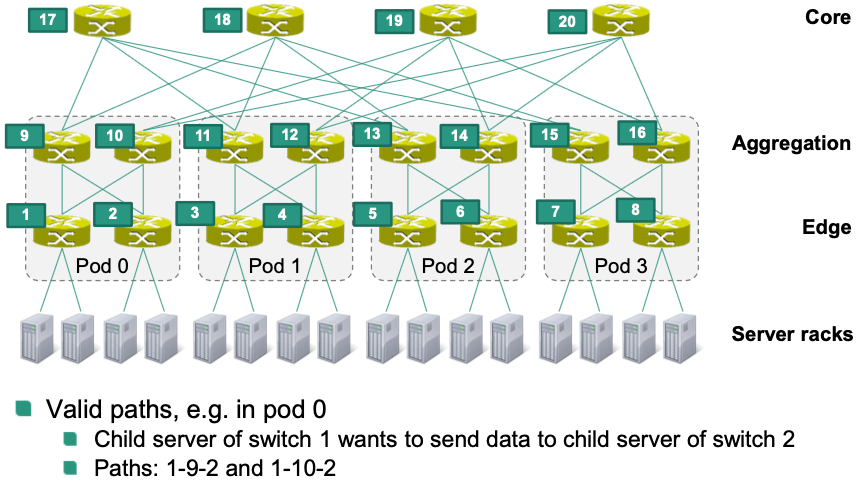
Routing Paths
Within a pod: $\frac{k}{2}$ paths from source to destination
- Example
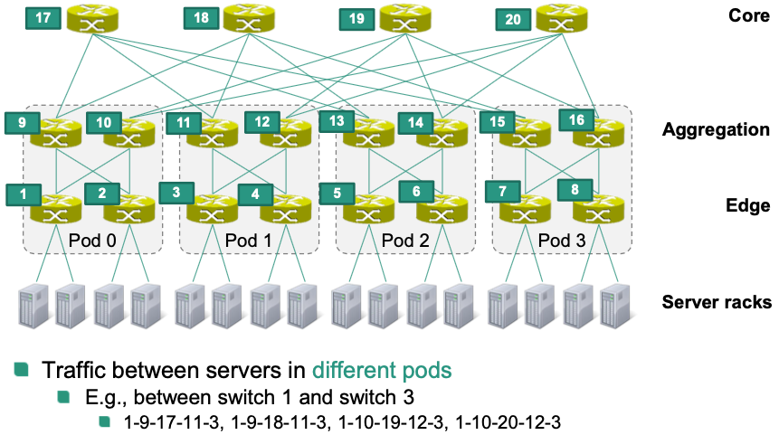
Between servers in different pods: $\frac{k^2}{4}$ ($= \frac{k}{2} \cdot \frac{k}{2}$) between servers in different pods
Example
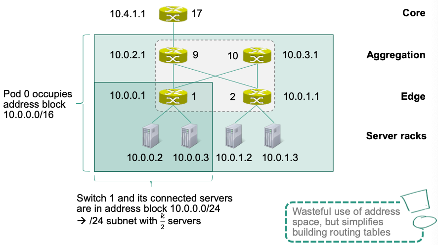
Address Assignment
Suppose assigning the private IPv4 address block 10.0.0.0/8
- Pods are enumerated from left to right: $[0, 𝑘 − 1]$
- Switches in a pod: IP address
10.pod.switch.1- Edge switches are enumerated from left to right: $[0, \frac{k}{2} - 1]$
- Enumeration continues with aggregation switches from left to right: $[ \frac{k}{2}, k - 1]$
- Switches in a pod: IP address
- Servers: IP address
10.pod.switch.ID- Based on the IP address of the connected edge switch
- IDs are assigned to servers from left to right starting with 2
- Core switches: IP address
10.k.x.yx: starts at 1 and increments every $\frac{k}{2}$ core switchesy: enumerates each switch in a block of $\frac{k}{2}$ core switches from left to right, starting with 1
Example: IP address assignment for pod 0
Two-level Routing Tables
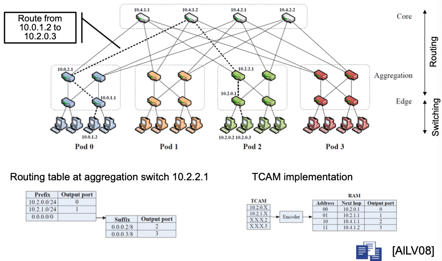
Example: HW17
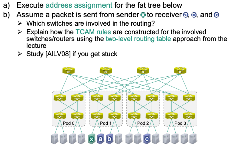
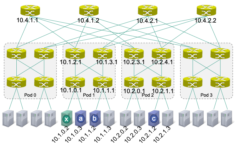
Solution for (a):
Solution for (b):
Use the following short-hand notation for the TCAM-based routing tables
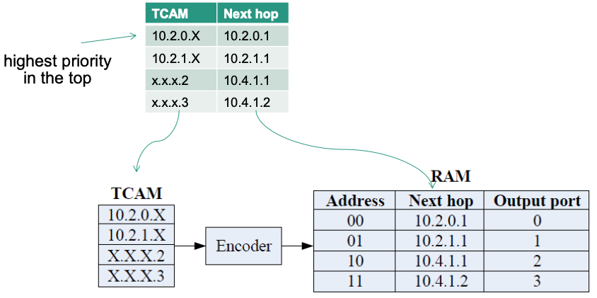
x –> a:
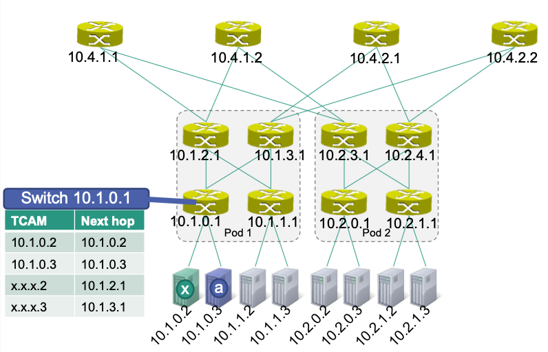
💡 Idea: if
x.x.x.2, then choose left; ifx.x.x.3then choose rightSwitch
10.1.0.1is connected with
- Server x (
10.1.0.2)- Server a (
10.1.0.3)- Aggregation switch
10.1.2.1- Aggregation switch
10.1.3.1In TCAM table
- For
10.1.0.2and10.1.0.3, there’s only ONE way to go- For
x.x.x.2(which is the first/left server connected to the edge switch), next hop will be the first/left connected aggregation switch (in this case,10.1.2.1)- For
x.x.x.3(which is the second/right server connected to the edge switch), next hop will be the second/right connected aggregation switch (in this case,10.1.3.1)
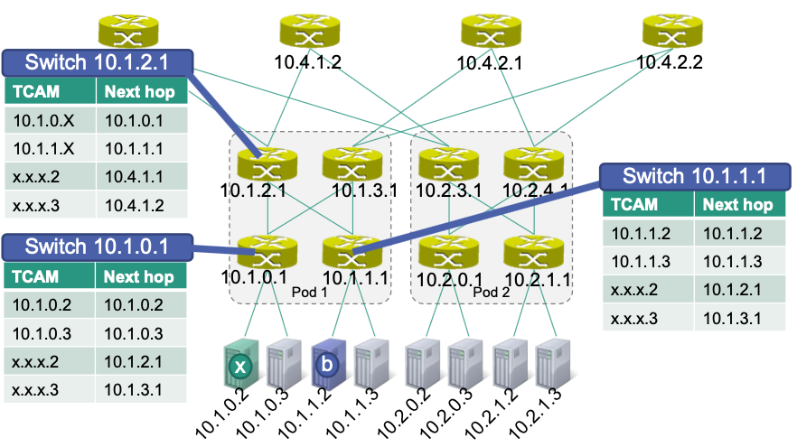
x –> b:
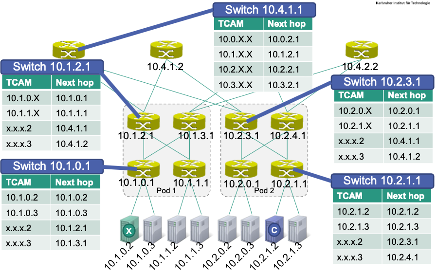
x –> c:
Ethernet
within Data Centers
🎯 Goal
Unification of network technologies in the context of data centers
Storage Area Networks (SANs)
HPC networking (High Performance Computing)
…
Ethernet as a “fabric” for data centers
- Has to cope with a mix of different types of traffic $\rightarrow$ Prioritization required
Data Center Bridging
Unified, Ethernet-based solution for a wide variety of data center applications
Extensions to Ethernet
Priority-based flow control (PFC)
Link level flow control independent for each priority
Enhanced transmission selection (ETS)
Assignment of bandwidth to traffic classes
Quantized congestion notification
Support for end-to-end congestion control
Data Center Bridge Exchange
Priority-based Flow Control (PFC)
🎯Objective: avoid data loss due to congestion
Simple flow control already provided by Ethernet: PAUSE frame
- All traffic on the corresponding port is paused
Priority flow control pause frame
Eight priority levels on one link
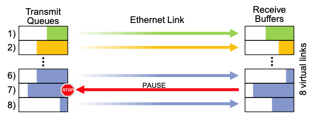
Use of VLAN identifier
$\rightarrow$ Eight virtual links on a physical link
Pause time can be individually selected for each priority level
$\rightarrow$ Differentiated quality of service possible 👏
Prioritization with Ethernet: Virtual LANs
Introduction of a new field for VLAN tags: Q header
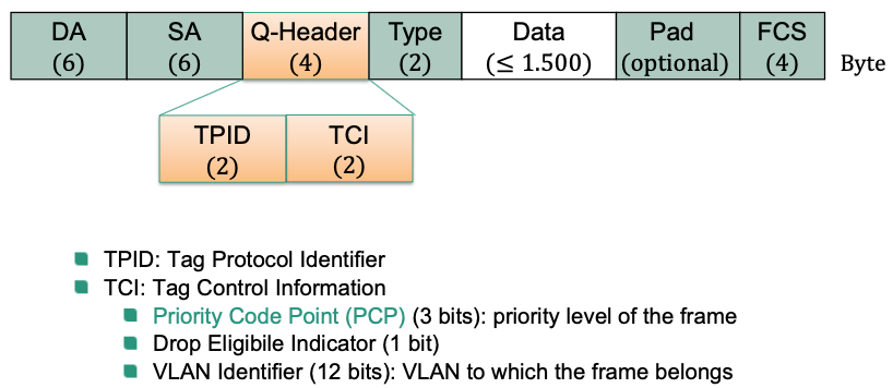
Differentiation of traffic according to priority chosen by PCP
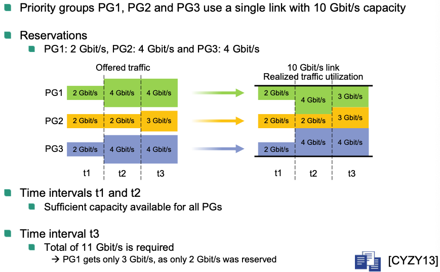
Enhanced Transmission Selection (ETS)
Reservation of bandwidth
- Introduction of priority groups (PGs)
Can contain multiple priority levels of a traffic type
Different virtual queues in the network interface
Traffic within one priority group can be handled differently
- Guarantee a minimum data rate per priority group
- Unused capacity usable by other priority groups
- Introduction of priority groups (PGs)
Example
Quantized Congestion Notification (QCN)
Can be used by switch to notify source node that causes congestion
- Note: PAUSE frame only send to neighbor node
Three main functions of QCN protocol
- Congestion detection
- Estimation of the strength of congestion
- Evaluation of buffer occupancy
- Predefined threshold reached $\rightarrow$ notification
- Congestion notification
- Feedback to congestion source via congestion notification message -
- Contains quantized feedback
- Feedback to congestion source via congestion notification message -
- Congestion response
- Source can limit data rate using a rate limiter
- Algorithm with additive increase, multiplicative decrease (AIMD) used
- Increase data rate (additive)
- Autonomously in absence of feedback
- Decrease data rate (multiplicative)
- Upon receipt of a congestion notification message
- Is lowered by a maximum of 50%
- Increase data rate (additive)
- Congestion detection
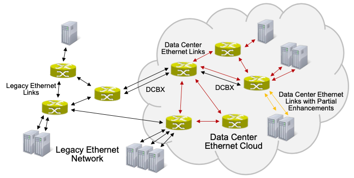
Data Center Bridge Exchange (DCBX) Protocol
Detection of capabilities and configuration of neighbors
For example, priority-based flow control
Periodic broadcasts to the neighbors
Beyond the Spanning Tree
🎯 Goals
- More flexibility in terms of network topology and usage
- Better utilization of the total available capacity
- Scalability for networks with many bridges
Various concepts developed
- Shortest Path Bridging (SPB)
- Transparent Interconnection of Lots of Links (TRILL)
Common characterstics of SPB and TRILL
- Provide multipath routing at layer 2
- Use of link state routing: modified Intermediate-System-to-Intermediate-System (IS-IS) protocol
- Use of en-/decapsulation of frames at domain border
Shortest Path Bridging
- Method
- Every bridge in the LAN calculates shortest paths
- Shortest path trees (unique identifier in the LAN)
- Paths have to be symmetric
- Learning of MAC addresses
- Support for equal cost multipath
- Same paths for unicast and multicast
- Every bridge in the LAN calculates shortest paths
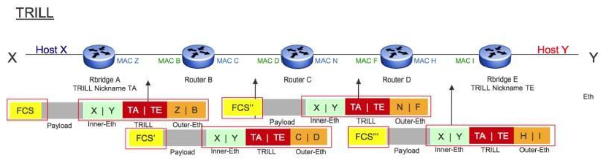
Transparent Interconnection of Lots of Links
Routing bridges (RBridges) implement TRILL
Each RBridge in the LAN calculates shortest routes to all other RBridges $\rightarrow$ Tree
Encapsulation example: data sent from S to D
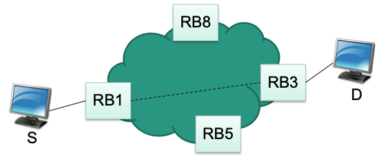
RBridge RB1 encapsulates frame from S
Specifies RBridge RB3 as the target because D is behind RB3
RBridge RB3 decapsulates frame
RBridges
Encapsulation: insert TRILL header
Resulting overall header

Outer Ethernet
- MAC addresses for point-to-point forwarding
- Change on every hop
Current source and destination Bridge MAC addresses
TRILL header includes among others
- Nickname fo ingress RBridge
- Nickname of egress RBridge
- Hop count
Nicknames of overall source (ingress) and destination (egress) bridges
Inner Ethernet: Source and destination MAC addresses of communicating end systems
MAC addresses of source and destination end systems
Example
TCP within Data Centers
Relevant Properties
Low round trip times (RTT)
Servers typically in close geographical proximity
Values in the range of microseconds instead of milliseconds
Incast communication
- Many-to-one: multiple sources transmit data to one sink (synchronized)
- Application examples: MapReduce, web search, advertising, recommendation systems …
Multiple paths
Mix of long-lived and short-lived flows
Little statistical multiplexing
Virtualization
Ethernet as a “fabric” for data centers
Commodity switches
Incast Problem in Data Centers
Incast: many-to-one communication pattern
- Request is distributed to multiple servers
- Servers respond almost synchronously
- Often, applications can not continue until all responses are received or do worse if no responses are provided
- Total number of responses can cause overflows in small switch buffers
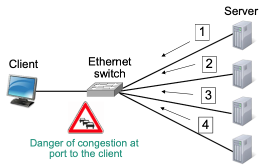
Packet Loss in Ethernet Switch
Situation
Ports often share buffers
Individual response may be small (a few kilobytes)
Packet losses in switch possible because
- Larger number of responses can overload a port
- High background traffic on same port as incast or
- High background traffic on a different port as incast
Packet loss causes TCP retransmission timeout
$\rightarrow$ no further data is received, so no duplicate acks can be generated
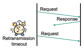
Barrier synchronization
slowest TCP connection determines efficiency
Affected TCP instance must wait for retransmission timeout
$\rightarrow$ Long periods where TCP connection can not transfer data
$\rightarrow$ Application blocked, i.e, response time increases
Improvements
- Smaller minimum retransmission timeout
- Desynchronization
Data Center TCP (DCTCP)
🎯 Goal: Achieve high burst tolerance, low latencies and high throughput with shallow-buffered commodity switches
Property: DCTCP works with low utilization of queues without reducing throughput
How does DCTCP achieve its goal?
- Responds to strength of congestion and not to its presence
- DCTCP
- Modifies explicit congestion notification (ECN)
- Estimates fraction of bytes that encountered congestion
- Scales TCP congestion window based on estimate
ECN in the Switch
Modified explicit congestion notification (ECN)
Very simple active queue management using a threshold parameter $K$
- If $\text{\# elements in queue} > K$: Set CE codepint
- Marking based on instantaneous rather than average queue length
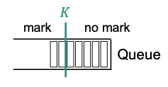
- Suggestion: $𝐾 > (𝑅𝑇𝑇 ∗ 𝐶)/7$
- $C$: data rate in packets/s
ECN Echo at the Receiver
New boolean TCP state variable: DCTCP Congestion Encountered (
DCTCP.CE)Receiving segments
If CE codepoint is set and
DCTCP.CEis falseSet DCTCP.CE to true
Send an immediate ACK
If CE codepoint is not set and
DCTCP.CEis trueSet DCTCP.CE to false
Send an immediate ACK
Otherwise: Ignore CE codepoint
Controller at the Sender
Estimates fraction of bytes sent that encountered congestion (
DCTCP.Alpha)Initialized to 1
Update:
$$ DCTCP. Apha=(1-g) * D C T C P . Alph a+g * M $$$g$: estimation gain ($0 < 𝑔 < 1$)
$M$: fraction of bytes sent that encountered congestion during previous observation window (approximately $RTT$)
$$ \mathrm{M}=\frac{ \text{ \# marked bytes }}{ \text { \# Bytes acked (total) }} $$
Update congestion window in case of congestion
$$ C W n d=(1-D C T C P . \text { Alpha } / 2) * C W n d $$- if $𝐷𝐶𝑇𝐶𝑃. 𝐴𝑙𝑝h𝑎$ close to 0, $𝐶𝑊𝑛𝑑$ is only slightly reduced
- if $𝐷𝐶𝑇𝐶𝑃. 𝐴𝑙𝑝h𝑎 = 1$, $𝐶𝑊𝑛𝑑$ is cut by factor 2
Handling of congestion window growth as in conventional TCP
Apply as usual
- Slow start, additive increase, recovery from lost packets
👍 Benefits of DCTCP
- Incast
- If number of small flows is too large, no congestion control will help
- If queue is built up over multiple RTTs, early reaction of DCTCP will help
- Queue buildup: DCTCP reacts if queue is longer than $𝐾$ (instantaneously)
- Reduces queueing delays
- Minimizes impact of long-lived flows on completion time of small flows connections
- More buffer space to absorb transient micro-bursts
- Buffer pressure
Queue of a loaded port is kept small
Mutual influence among ports is reduced in shared memory switches